Improving the federal intelligence and control system airspace: history, reality, prospects
At the end of the 20th century, the issue of creating a single radar field of the country was quite acute. Multi-departmental radar systems and means, often duplicating each other and eating up colossal budget funds, did not meet the requirements of the country's leadership and the Armed Forces. The need to expand work in this area was obvious.
The start of work on the creation of a federal system of reconnaissance and airspace control was laid by a presidential decree. Russian Federation 1993 "On the organization of air defense in the Russian Federation", in which for the first time the now familiar name sounded - the federal system of reconnaissance and control of the airspace of the Russian Federation (FSR and KVP).
The Military Scientific Committee and the Directorate of Radio Engineering Troops (RTV) of the High Command of the Air Defense Forces prepared draft reports and regulatory legal documents that formed the basis of the decrees of the President of the Russian Federation in 1994 “On the creation of a federal system for reconnaissance and control of the airspace of the Russian Federation” and “ On Approval of the Regulations on the Central Interdepartmental Commission of the Federal System of Intelligence and Airspace Control of the Russian Federation”.
The following tasks were assigned to the FSR and KVP:
- radar reconnaissance and radar control of the airspace of the Russian Federation;
- operational control of the forces and means of radar reconnaissance and radar control of airspace;
- organization of interaction between the command and control bodies of the branches of the Armed Forces of the Russian Federation (RF Armed Forces) and air traffic control bodies;
- information support for command and control systems and air traffic control;
- placement on the territory of the Russian Federation of radio-electronic equipment on the basis of a unified technical policy.
The information base of the FSR and the KVP was made up of units of the RTV air defense, communications and radio support troops of the Air Force, radar surveillance of the Navy, radar positions of the Unified Organization System air traffic(EU ATM). The radar reconnaissance units of the Air Defense Forces of the Ground Forces could be used by special order.
Thus, the unified radar system of the federal system was to consist of the forces and means of radar reconnaissance of the Ministry of Defense of the Russian Federation and the Ministry of Transport of the Russian Federation, as well as the control system, collection and processing of radar information, which was based on command posts (CP) of radio engineering units and formations , reconnaissance and information centers of the command posts of formations and associations (districts and zones) of air defense.
In its development, the FSR and KVP, as its ideologists imagined, had to go through a number of stages of development, while it was necessary to maximize the potential of the radar system of the RF Armed Forces:
1st stage. Preparatory (1993).
2nd stage. Priority work on the creation of the FSR and KVP (January - September 1994).
3rd stage. Deployment of the main elements of the FSR and KVP in the air defense zones (October - December 1994).
4th stage. Deployment of dual-purpose information elements and testing of technical means of a unified automated radar system - EA RLS (1995-2001).
5th stage. Complete transition to EA radar (2001–2005).
FSR and KVP was formed two decades. Practical work on the creation of a federal system began in October 1994, when, on behalf of the President of Russia, the central interdepartmental commission of the FSR and KVP (TsMVK) began to function under the leadership of the Commander-in-Chief of the Air Defense Forces, Colonel-General of Aviation V. A. Prudnikov. The origins of the creation of the federal system were professionals in their field, military and civilian leaders and specialists in the field of air defense and air traffic control: V. A. Prudnikov, V. G. Shelkovnikov, V. P. Sinitsyn, V. F. Migunov, G. K. Dubrov, A. I. Aleshin, A. R. Balychev, Ya. V. Bezel, V. I. Mazov, A. S. Sumin, V. P. Zhyla, V. K. Demedyuk, V. I. Ivasenko, V. I. Kozlov, S. N. Karas, V. M. Korenkov, A. E. Kislukha, B. V. Mikhailov, B. I. Kushneruk, N. F. Zobov, A. A. Koptsev, R. L. Danelov, N. N. Titarenko, A. I. Travnikov, A. I. Popov, B. V. Vasiliev, V. I. Zakharyin and others.
During the first four stages, coordinating bodies of the federal system were created and began to work: the TsMVK FSR and KVP, six zonal interdepartmental commissions (for air defense zones), two interdepartmental commissions - with the rights of zonal ones (in two air defense districts in the west and east of the country).
Regulatory legal documents were developed and approved to regulate the creation of dual-use information elements of the FSR and KVP in air defense zones and areas: “Regulations on the dual-use units of the Russian Ministry of Defense”, “Regulations on the positions of the Russian Ministry of Transport dual-use”, General agreement between the Russian Ministry of Defense and the Ministry of Transport of Russia "On the Creation, Functioning and Operation of Dual-Use Units and Positions".
Rice. 1. Evaluation of the reduction in the resource consumption of radio-electronic equipment RTV Air Force
Graphics by Yulia GORELOVA
As a result of this work, agreements were reached between the authorized structures of the Russian Ministry of Defense and the Russian Ministry of Transport on the creation of 30 positions and 10 dual-use units.
The first practical steps towards the creation of dual-use information elements of the federal system were made thanks to the perseverance and enthusiasm of the specialists of the radio engineering troops (RTV), who served as the apparatus of the TsMVK, as well as EU ATM enterprises and enterprises of the military-industrial complex (DIC).
The experience of information interaction between military and civilian authorities has shown that the use of dual-use units of the RTV in n. The settlements of Chalna, Komsomolsk-on-Amur, Kyzyl, Kosh-Agach made it possible to reduce the economic costs of enterprises in the interests of solving the problems of the EU ATM by at least 25–30 percent. Radars (RLK) RTV types 5N87, 1L117 and P-37 were used as sources of radar information.
In turn, the use of the TRLK-10 and the P-37 radar at the dual-purpose positions of the North Caucasus Air Traffic Control Center, Khabarovsk, Vladivostok, Perm, Kolpashevo ATM centers made it possible to maintain the quality of control over the procedure for using airspace within the boundaries of responsibility for air defense in the face of a reduction in the composition and the number of RTV Air Force.
However, the topics of the FSR and KVP, despite the very high level documents, in accordance with which it was necessary to conduct work, was financed within the framework of the state defense order on a residual basis. And R&D for SDF and KVP in these years were financed at the level of 15 percent of the need.

Radio altimeter PRV-13 at one of the sites of the Kapustin Yar test site. It was intended to work as a means of measuring height as part of the 5N87 radar complex together with other rangefinders (P-37, P-35M, 5N84, 5N84A)
Photo: Leonid YAKUTIN
As of July 1, 1997, it was not possible to conclude a single agreement (local agreement) on the creation of dual-use information elements due to the lack of real opportunities for mutual settlements between military and civilian users of radar information.
There is an urgent need to have priority funding when creating a federal system. Therefore, in December 1998, a special working group was formed from representatives of the apparatus of the Security Council of the Russian Federation, the Russian Ministry of Defense and the Federal aviation service(FAS) of Russia, which prepared an analytical note on the FSR and KVP for a report to the country's top leadership.
The note noted that the situation with the creation of the FSR and the CVP poses not only a serious threat to Russia's national security, but is also the reason for the loss of profit from possible revenues Money to the federal budget through the FAS Russia from foreign and domestic airlines using Russian airspace.
It was stated that the FSR and KVP is the national treasure of Russia, one of the most important fragments of the country's single information space. She needed to provide immediate and comprehensive state support.

Rice. 2. Indicators of the increase in the area of controlled airspace
Graphics by Yulia GORELOVA
The issue was resolved at the level of Prime Minister of the Russian Federation E. M. Primakov. In the shortest possible time, the materials of the analytical note were considered at all levels and instructions were given for further actions. The Ministry of Defense of Russia, together with interested departments, prepared and agreed on projects required documents and in August 1999, a decree of the President of the Russian Federation "On priority measures of state support for the federal system of reconnaissance and control of the airspace of the Russian Federation" was issued.
The decree identified state customers and the lead contractor for improving the unified radar system of the FSR and KVP. The Government of the Russian Federation was instructed to ensure the development and approval in 1999 of the Federal Target Program (FTP) for improving the FSR and CVP for 2000-2010, providing for the financing of this program from the federal budget.
For several years, the draft FTP was considered, corrected, clarified, shortened, supplemented, but not submitted for consideration by the government. In 2001, the Main Control Directorate of the President of the Russian Federation became interested in how the decisions taken on the creation of the FSR and the CVP were implemented, and conducted an inspection of the state of affairs.
The audit showed that the government and a number of ministries (the Ministry of Defense of Russia, the Federal Antimonopoly Service of Russia, the Ministry of Economic Development of Russia, the Ministry of Finance of Russia) did not take proper measures to implement the adopted regulatory legal acts. The state of affairs in the creation of the FSR and the KVP was recognized as unsatisfactory and inconsistent with the requirements of national security. It was recommended that urgent measures be taken to remedy the situation. However, even such a harsh assessment did not change the situation for the better.
However, life did not stand still. Troops and enterprises for the use of airspace and air traffic control had to be given some kind of tool for equipping dual-use information elements with dual-purpose route radar systems (TRLC DN).
Specialists of interested structures of the Ministry of Defense of Russia, the Ministry of Transport of Russia and the Ministry of Economic Development of Russia prepared a draft decision on shared financing of equipping dual-purpose route radar positions (TRLP DN), which was submitted to the Air Force Commander-in-Chief for approval by the heads of the Ministry of Defense of the Russian Federation and the Ministry of Transport of the Russian Federation.

PRV-13 were also used as part of the automated radio engineering units of the automated control systems 5N55M (Mezha-M), 5N53-N (Nizina-N), 5N53-U (Nizina-U) of the Luch-2 (3) system ,86Zh6 ("Field"), 5N60 ("Basis") of the Luch-4 system. PRV-13 interfaced with objects ACS "Vozdukh-1M", "Vozdukh-1P" (with equipment for retrieval and transmission of data ASPD and instrument guidance equipment "Kaskad-M"), with ACS ZRV ASURK-1MA, ASURK-1P and cockpit K -9 ZRS S-200
Photo: Leonid YAKUTIN
The decision was approved in November 2003. Starting from 2004, it was envisaged to finance the equipping of the DN TRLP on the principles of equity participation within the framework of the state defense order and the Unified Air Traffic Management System subprogram of the Federal Target Program “Modernization transport system Russia (2002–2010)”.
The equipment for equipping the DN TRLP was determined to be the Lira-T TRLC DN manufactured by Lianozovsky Electromechanical Plant OJSC. In accordance with this decision, taking into account the absence of FTPs for FSR and KVP, work was carried out over several years. The main technical solutions for equipping the Lira-T TRLC DN were tested during state tests on the Velikie Luki DP TRLC. For the period 2004–2006 more than a dozen DN TRLP were equipped: in 2004 - Omolon, Markovo, Kepervey, Pevek, m. Schmidt; in 2005 - Okhotsk, Okha, Nakhodka, Arkhara; in 2006 - m. Kamenny, Polyarny, Dalnerechensk, Ulan-Ude.
The work done made it possible to have 45 dual-use information items by the end of 2006 (33 percent of the approved lists). This result was achieved to a large extent thanks to the active position of the CMAC, which in different years led by the current commanders-in-chief of the Air Defense Forces, and since 1998 - the Air Force.
The main burden of organizational and technical support for the creation of the FSR and the CVP fell on the apparatus of the TsMVK, the functions of which were performed by the RTV Department. In 2003, the specially created 136th Coordinating and Regulatory Department (CNO) of the FSR and the KVP of the Air Force became the center of this very important work.
The management of the department was entrusted to A.E. Kislukha, who since 1994 was the executive secretary of the TsMVK and led the functional direction of work on the creation of elements of the federal system in the RTV Directorate of the High Command of the Air Defense Forces, and later - the Air Force.
The formation of the KNO, of course, removed a number of problems of coordinating the work of various departments, but the department did not solve the main task of testing technical means. Due to this and a number of other reasons, it was not possible to solve the main problem of technical re-equipment with dual-use means and transition to EA radar by 2005. The determining factor was the lack of targeted funding for research, development and serial deliveries of dual-use technical means to improve the FSR and KVP.
It was only in January 2006 that the concept of the Federal Target Program “Improvement of the federal system of reconnaissance and control of the airspace of the Russian Federation for the period up to 2010” was approved by the order of the government of the Russian Federation, and then in June of the same year, the decree of the government of the Russian Federation No. 345 “On federal target program "Improvement of the federal system of reconnaissance and airspace control of the Russian Federation (2007-2010)".

Three-coordinate combat mode radar station (centimeter radio wave range) ST-68UM
Photo: Leonid YAKUTIN
A lot of work on the preparation of draft documents was carried out by the leaders and specialists of the Air Force High Command: A. V. Boyarintsev, A. I. Aleshin, G. I. Nimira, A. V. Pankov, S. V. Grinko, specialists from the production and technological policy department and civilian products (PTP PGN) JSC Air Defense Concern Almaz-Antey: G. P. Bendersky, A. I. Ponomarenko, E. G. Yakovlev, V. V. Khramov, O. O. Gapotchenko, heads and specialists of the Ministry of Transport of the Russian Federation: A. V. Shramchenko, D. V. Savitsky, E. A. Voytovsky, N. N. Titarenko, N. I. Torba, A. Lomakin, as well as managers and specialists of the State ATM Corporation »: V. R. Gulchenko, V. M. Libov, K. K. Kaplya, V. V. Zakharov, K. V. Elistratov.
The concept of the development of the FSR and CVP of the Russian Federation for the period up to 2015 and beyond determined the main directions of the organizational, military-technical and economic policy for the development of the FSR and CVP in the interests of solving the tasks of the Aerospace Defense, organizing air traffic and suppressing terrorist acts and other illegal actions in airspace of the Russian Federation.
The concept reflects the coordinated positions of the Ministry of Defense of the Russian Federation, the Ministry of Transport of the Russian Federation, as well as other interested federal executive bodies in the main areas of development and application of the FSR and KVP in Peaceful time.
Ideologically, a new phasing in the development of the FSR and KVP was recognized. In its development, the SRF and CWP must go through five main stages:
- Stage I - 1994–2005;
- Stage II - 2006–2010;
- Stage III - short-term perspective (2011-2015);
- Stage IV - medium term (2016–2020);
- Stage V - long-term perspective (after 2020).
At stage I From the moment of the creation of the FSR and the KVP, the principle of the coordinated use of radar facilities of the Russian Ministry of Defense and the Russian Ministry of Transport in areas of joint deployment was laid as the basis for building a federal system in accordance with the regulatory legal documents in force at that time. The implementation of this principle was achieved by centralized (unified) planning of the use of radar facilities in air defense zones (regions).
At the same time, the exchange of information about the air situation between the dual-purpose radio engineering units (RTP DN) of the Russian Ministry of Defense and regional centers of the EU ATM, as well as between the dual-use radar positions (RLP DN) of the Ministry of Transport of Russia and the radio engineering units of the Air Force and Navy was carried out mainly in a non-automated way.
The source of funding for work related to the creation and use of dual-use units and positions was the funds received by the Ministry of Transport of Russia at the expense of air navigation fees, as well as funds allocated by the Russian Ministry of Defense for the construction and maintenance of the RF Armed Forces.
The absence of a mechanism for targeted financing of measures to create the FSR and the STOL did not allow organizing the use of information about the air situation from the EU ATM radar station located in areas where the air defense forces on duty of the Russian Ministry of Defense do not create a radar field. This factor, as well as the lack of information-technical interaction (interfacing) of the automated systems of the EU ATM and air defense authorities, did not lead to a significant increase in the efficiency of the functioning of the FSR and STOL.
At stage II creation and development of the FSR and CVP, after many years of efforts, guaranteed state support for the deployment of the FSR and CVP was finally achieved within the framework of the Federal Target Program “Improvement of the FSR and CVP of the Russian Federation (2007–2010)”.
Three main areas of activity were planned:
1. Comprehensive work to improve the FSR and KVP, including:
- development of project documentation for information interaction between EU ATM centers and air defense control bodies;
- development of documentation for the reconstruction of EU ATM centers;
- development of project documentation for the reconstruction of dual-purpose en-route radar positions of the EU ATM.
2. Reconstruction of dual-purpose en-route radar positions of the EU ATM.
3. Reconstruction of EU ATM centers in terms of equipping SITV with air defense controls.
The main objective of the FTP is the creation of the material and technical base of the FSR and KVP in the Central, North-Western and Eastern regions of the Russian Federation by equipping the EU ATM Training Center with information and technical interaction systems (ITV) with air defense control bodies, as well as modernizing the RLP of the Ministry of Transport of Russia to perform dual-use functions.
The overall coordination of the activities of the FSR and KVP at the second stage of its development was entrusted to the Interdepartmental Commission for the Use and Control of the Airspace of the Russian Federation, formed by decree of the President of the Russian Federation in 2006.
The publication in 2008 of the Decree of the President of the Russian Federation “On measures to improve the management of the federal system of reconnaissance and control of the airspace of the Russian Federation” became a significant help in the work.
The Decree legally fixed the organizational and technical changes in the field of FSR and STOL, which actually occurred after the emergence of a new coordinating body in the person of the Interdepartmental Commission for the Use and Control of the Airspace of the Russian Federation (MVK IVP and STOL), and also established that the only supplier (head contractor) when placing orders for the supply of goods, performance of work, provision of services for state needs in the interests of the defense of the country and the economy of the state in the field of use, reconnaissance and control of the airspace of the Russian Federation, JSC Air Defense Concern Almaz-Antey is.
In the course of the implementation of the FTP, much attention was paid to the issue of creating SITS, in order to achieve the effectiveness of which a typical structural diagram of SITS of EU ATM centers with controls and an air defense command post was developed. The scheme provides for the implementation of two ways of issuing information about the air situation from dual-use information elements: centralized and decentralized.
To organize direct interaction between the EU ATM center and air defense units, a communication dispatcher is appointed from the combat crew of the duty shift of the command post of the air defense formation. The dispatcher's workplace for interaction with air defense authorities is installed in the EU ATM center and includes technical means for displaying radar and planning and dispatching information and means for communicating with officials of the EU ATM center and air defense command post.
This decision has stood the test of time (1999–2005). The so-called elbow interaction of officers of the control bodies of the air defense command post with air traffic controllers was carried out directly at the EU ATM centers in the air defense zones. The proposed technical solutions within the framework of the FTP significantly increase the possibilities of interaction.
The technical solution of the problem of information and technical interaction is based on a complex of software and hardware tools (CPTS), which makes it possible to receive radar and planned dispatch information from automated air traffic control systems (ATC) of EU ATM centers, as well as receive, process and combine radar information from the TRLP DN, which are part of the EU ATM center, for subsequent transfer to the automation equipment complexes of the air defense command post.
The technical means of SITV also include remote sets of user equipment (VKAO), complexes of means of communication and transmission of data on the air situation (KSSPD). The methodological apparatus for designing and evaluating indicators and indicators of the FTP, which was used in the design of the FTP measures, was developed at the 2nd Central Research Institute of the Ministry of Defense of the Russian Federation, the State Research Institute "Aeronavigation" and the Scientific and Technical Center "Promtechaero".
In order to perform the complex of works provided for by the FTP, a cooperation of co-executors was created at the Air Defense Concern Almaz-Antey, which included more than 10 enterprises and organizations. A large amount of work in the main areas of activity was carried out by the PTP Department of PGN, MNIIPA, VNIIRA, NITA, NPO Lianozovsky Electromechanical Plant, Scientific and Technical Center Promtekhaero, LOTES-TM, Radiophysics, State Research Institute Aeronavigation, 24th NEIU and the 2nd Central Research Institute of the Ministry of Defense of the Russian Federation.
For the purpose of reconstruction of the DN TRRL based on the requirements of the Ministry of Defense of Russia and the Ministry of Transport of Russia, JSC NPO Lianozovsky Electromechanical Plant specially developed and successfully passed state tests of the Sopka-2 TRLC DN.
TRLK DN "Sopka-2" is designed to equip dual-use radar positions of the Ministry of Transport of Russia and provide radar information to launchers of the RF Armed Forces, involved in peacetime on combat duty for air defense, to solve the problems of detection, measuring three coordinates, assessing movement parameters, determining nationality air objects, as well as obtaining additional (flight) information and receiving “Alarm” (“Distress”) signals from aircraft located in its coverage area, and issuing generalized information about the air situation to display facilities or to the EU ATC ATC system and to KP (PU) RF Armed Forces.
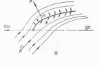
The work performed during the II stage of the work on the deployment of SITS in nine EU ATM centers (Moscow, Khabarovsk, Vladivostok, Petropavlovsk-Kamchatsky, Magadan, Yakutsk, Rostov, St. - In the western regions of the country, fragments of a single radar system of the FSR and KVP, built on the principle of information and technical interaction between departmental radar systems of the Russian Ministry of Defense and the Russian Ministry of Transport.
At the same time, the exchange of information about the air situation between the EU ATM centers equipped with SITS and the command posts of the aerospace defense brigades is carried out in an automated mode, and most of the modernized positions are deployed by DN TLKs, which include equipment for state identification of the EU GRLO and measurement of the flight altitude of the observed VO. The work carried out at the II stage to improve the FSR and KVP made it possible to increase the area of air space controlled by the Russian Ministry of Defense (at an altitude of 1000 meters) by more than 1.7 million square meters. km, reduce the resource consumption of radio-electronic equipment of the Russian Ministry of Defense by almost 1.4 million hours and ensure the required level of air traffic safety by reducing the risk of disasters from 13x10 -7 to 4x10 -7.
The end follows.
Alexander KISLUKHA
MILITARY THOUGHT No. 4/2000 Pg. 30-33
Federal system of reconnaissance and airspace control: problems of improvement
Lieutenant General A.V. SHRAMCHENKO
Colonel V.P. SAUSHKIN, candidate of military sciences
An IMPORTANT component of ensuring the national security of the Russian Federation and the safety of air traffic over the territory of the country is radar reconnaissance and airspace control. The key role in solving this problem belongs to the radar facilities and systems of the Ministry of Defense and the Federal Service. air transport(FSVT).
At the present stage, when issues of rational use of material and financial resources allocated for defense, conservation of weapons resources and military equipment, the main direction in the development of radar facilities and systems should be considered not the creation of new ones, but the organization of a more efficient integrated use of existing ones. This circumstance predetermined the need to concentrate the efforts of various departments on the integration of radar facilities and systems into the Unified Automated Radar System (EARLS) within the framework of the Federal System for Reconnaissance and Airspace Control (FSR and KVP) of the Russian Federation.
Developed in accordance with the Decree of the President of Russia, the federal target program for improving the FSR and CVP for 2000-2010 proclaims its goal to achieve the required efficiency and quality of solving the problems of air defense, protection of the state border of the Russian Federation in the airspace, radar support for aviation flights and air traffic management at the most important air directions based on the integrated use of radar facilities and systems of the types of the RF Armed Forces and the Federal Air Transport Service in the context of a reduction in the total composition of forces, means and resources.
The main task of the first stage of improving the FSR and CVP (2000-2005) is the creation of EARLS in the Central and North Caucasian air defense zones, in the Kaliningrad air defense region (Baltic Fleet), in certain areas of the North-Western and Eastern air defense zones on the basis of complex equipment of groups troops and positions of the FSVT with unified means of automation of interspecific use.
For this, it is planned, first of all, to develop concepts for the development of radar detection equipment to equip the EARLS and a unified system for displaying the underwater, surface and air situation in maritime theaters. Particular attention will be paid to the system engineering issues of building a real-time information exchange system for FSR and KVP on the basis of existing and prospective means.
During this period, it is necessary to master the mass production of radar equipment that has passed state tests, unified complexes of automation equipment (KSA) for interspecific use in stationary and mobile versions, and to begin systematic equipping of groupings of troops with them in accordance with the strategy for creating the EARLS. In addition, it is necessary to determine the composition organizational structure and arming the mobile reserve of the FSR and KBIT of constant readiness, as well as a list of radio engineering units of the coastal surveillance service of the Navy for inclusion in the FSR and KVP, develop proposals and plans for their phased rearmament. It is necessary to carry out measures to modernize radio-electronic equipment, extend its service life and maintain the existing fleet in good condition, R&D aimed at creating priority promising models of interspecific application, develop norms (standards and recommendations) for basic equipment options for units of the Ministry of Defense and positions of the dual-use FS VT, in according to which they were retrofitted.
The result of the work should be the testing of experimental sections of EARLS fragments, their retrofitting with unified information exchange complexes, and the dissemination of the experience gained to other air defense zones and regions.
At the second stage(2006-2010) it is planned to complete the formation of EARLS in the North-Western and Eastern air defense zones; creation of EARLS fragments in certain areas of the Ural and Siberian air defense zones; creation of a mobile reserve of FSR and KVP of constant readiness, its equipping with mobile radars and KSA of interspecific use; completion of R&D on the development of priority promising models of radio-electronic equipment for interspecific use and the beginning of the systematic equipping of the FSR and KVP with them; completion of building an information exchange system for the FSR and KVP as a whole; carrying out research and development on the development of unified block-modular radars and KSA of interspecific application; creation of a scientific and technical reserve for further development and improvement of the SRF and KVP.
It should be noted that the strict departmental subordination of the radar equipment of the types of the RF Armed Forces and the Federal Military Service, in combination with the low level of automation of the processes of controlling the forces and means of radar reconnaissance, makes it difficult to build the FSR and KVP according to a single plan and plan, and especially the adoption of optimal decisions on its use in the interests of all consumers of radar information. Thus, indicators of the effectiveness of the use of FSR and KVP in solving functional problems, regularities and principles of management, powers and limits of responsibility of command and control bodies for managing the forces and means of radar reconnaissance in peacetime, during combat duty and in the process of combat use, have not been determined.
The complexity of identifying the patterns and principles of managing the FSR and CVP is due to insufficient experience in its use. It is required to create an appropriate terminology with the choice of the most accurate definitions of the basic concepts related to radar. Nevertheless, certain views have developed on the principles of managing complex organizational and technical systems, the organization and methods of work of management bodies, taking into account the prospects for the development and implementation of automated control systems. A wealth of experience has been accumulated in solving the problems of controlling radar facilities and systems in the branches of the Armed Forces of the Russian Federation and the Federal Military Service.
In our opinion, the management of the FSR and KVP should be a set of coordinated measures and actions of the management bodies of the FSR and KVP to maintain subordinate forces and means in constant readiness for their use and guide them in the performance of their tasks. It should be carried out taking into account the requirements of all interested parties on the basis of automation of the processes of collecting, processing and distributing information at all levels.
Studies have shown that, first, only central planning and control forces and means FSR And STOL will allow, at a given level of efficiency, to preserve the reserve of the technical resource of radio-electronic equipment to the maximum, reduce the number of maintenance personnel, create a unified system of operation, repair and logistics, and significantly reduce operating costs; Secondly, organizational structure and methods of management should be those in which the possibilities of technical means are used to the maximum extent to achieve the goals of management; thirdly, only complex automation of management processes And use of optimization models allow to achieve a significant increase in the efficiency of the application FSR And STOL compared to traditional heuristic methods of planning and management.
The main principles of the management of the SRF and KVP, in our opinion, should be centralization and unity of command. Indeed, the dynamism and transience of changes in the air and electronic situation, especially in the conditions of warfare, have significantly increased the role of the time factor and the need sole decision making and firmly putting it into practice. And this can be achieved only with a strict centralization of rights in the hands of one person. Centralization of management will allow in a short time and the best way coordinate the actions of diverse forces and means FSR and CVP, apply them effectively, quickly concentrate efforts on the main directions, on the solution of the main tasks. At the same time, centralized management should be combined with the provision of initiative to subordinates in determining how to perform the tasks assigned to them.
The need for unity of command and centralization of management also follows from the very goals of creating FSR and KVP, which are the reduction in the total costs of the Ministry of Defense and FSVT for holding R&D for the development of automation and radar equipment, for the maintenance and development of positions of radar facilities; unified understanding of the air situation in the control bodies of all levels; ensuring radio-electronic compatibility of means of radar and communication of types RF Armed Forces and FSVT in joint basing areas; reduction in the type and unification of radar facilities, KSA and communications facilities, the creation of uniform standards for their interface.
Since the foundation FSR And STOL make up the radio engineering troops Air Force, general leadership creation and the use of FSR and KVP, it is advisable to assign to the Commander-in-Chief of the Air Force, who, as chairman of the Central Interdepartmental Commission FSR And STOL can administer FSR And KVP. The tasks of the commission should include: development of development plans FSR And STOL and coordination of R&D in this area, taking into account the main directions for improving the forces and means of radar reconnaissance of types RF Armed Forces and FSVT; implementation of a unified technical policy with the phased creation FSR And STOL, development of proposals and recommendations to the branches of the Armed Forces of the Russian Federation and the Federal Service for Military Transport in the areas of development of radar, automation and communications, their standardization and compatibility; development of programs and plans for equipping the FSR and KVP with technical means that provide a high-quality solution to peacetime and wartime tasks, organizing work on certification, attestation and licensing of technical means; harmonization with the branches of the Armed Forces and the FSMFT of the normative and legal documents being developed that regulate the functioning of the FSR and the CVP; coordinated planning and formation of orders for serial production, purchase of new equipment for the FSR and KVP and its deployment; planning and organization of the use of FSR and KVP in the interests of all interested consumers of radar information; coordination with the branches of the Armed Forces of the Russian Federation and the FSVT of issues related to the deployment and redeployment of radar units.
The Commander-in-Chief of the Air Force can exercise direct control over the creation and improvement of the FSR and CVP through the Air Force Radio Engineering Troops Directorate, which performs the functions of the apparatus of the Central Interdepartmental Commission.
General guidance on the use of SRF and KVP in air defense zones it is advisable to lay on the commanders of the Air Force formations, in air defense areas - on commanders of air defense formations, who can manage the FSR and KVP personally, through the zonal interdepartmental commissions of the FSR and KVP, the headquarters of the Air Force formations and air defense formations, as well as through their deputies and chiefs of the radio engineering troops.
The tasks of the zonal interdepartmental commission of the FSR and KVP, the headquarters of the Air Force formation (air defense formations) should include: planning and organizing combat duty of a part of the forces and means of the FSR and KVP in the air defense zone (region); coordination of plans for the use of FSR and KVP in the air defense zone (area) with all interested departments; organizing and conducting training of personnel and equipment of the FSR and KVP for the fulfillment of assigned tasks; organization of radar reconnaissance and airspace control of the FSR and KVP in the air defense zone (area); control over the quality and stability of the provision of radar information to the authorities; organization of interaction with the forces and means of reconnaissance and airspace control, which are not part of the FSR and STOL; coordination of the issues of operation of technical means of the FSR and KVP.
Structurally, the control system of the FSR and KVP should include controls, control posts, a communication system, complexes of automation equipment, etc. In our opinion, it can be based on the control system of the radio engineering troops of the Air Force.
Immediate control it is expedient to produce by forces and means of radar reconnaissance and airspace control from the existing command posts of the services of the Armed Forces and the Federal Air Transport Service (according to departmental affiliation). At the same time, they must organize their work and the work of subordinate forces and means in accordance with the requirements of consumers of radar information on the basis of a unified planning for the use of FSR and KVP in zones and areas air defense.
In the course of combat use, the radio engineering units (radar positions) of the FSR and the KVP on issues of conducting radar reconnaissance and issuing radar information must be promptly subordinate to the command and control bodies of the radio engineering troops of the Air Force through the command posts of the corresponding branches of the Armed Forces.
In the context of the ever-increasing dynamism of the air and electronic situation and the active influence of the opposing side on radar assets and systems, the requirements for ensuring their effective control are sharply increasing. It is possible to radically solve the problem of increasing the efficiency of the use of FSR and KVP only through complex automation of management processes based on the implementation new information technologies. A clear formulation of the goals of the functioning of the FSR and KVP, management tasks, the definition of target functions, the development of models adequate to the objects of management - these are the main problems that need to be solved when synthesizing the structure of the management system and algorithms for its functioning, distributing functions by levels of the management system and determining their optimal composition.
military thought. 1999. No. 6. S. 20-21.
To comment, you must register on the site.
Impossible without the creation of an effective system of reconnaissance and airspace control. An important place in it is occupied by a low-altitude location. The reduction of units and means of radar reconnaissance has led to the fact that over the territory of Russia today there are open sections of the state border and the country's interior.
OJSC NPP Kant, which is part of the Russian Technologies State Corporation, is conducting research and development to create a prototype of a multi-position diversity radar system for semi-active location in the radiation field of systems cellular communication, broadcasting and television terrestrial and space-based ( complex "Rubezh").
Today, the greatly increased accuracy of targeting weapons systems no longer requires the massive use of air attack weapons (AOS), and the tightened requirements for electromagnetic compatibility, as well as sanitary norms and rules, do not allow in peacetime to “contaminate” the populated areas of the country with the use of microwave radiation (UHF radiation) high-potential radar stations (RLS).
In accordance with the federal law "On the sanitary and epidemiological well-being of the population" dated March 30, 1999 No. 52-FZ, radiation standards have been established that are mandatory throughout Russia. The radiation power of any of the known air defense radars many times exceeds these standards. The problem is aggravated by the high probability of using low-flying low-observable targets, which requires the compaction of the combat formations of the traditional fleet radars and the increase in the cost of maintaining a continuous low-altitude radar field (SVRLP).
To create a continuous duty round-the-clock MSRLP with a height of 25 meters (the flight altitude of a cruise missile or an ultralight aircraft) along a front of only 100 kilometers, at least two radars of the KASTA-2E2 (39N6) type are required, the power consumption of each of which is 23 kW. Taking into account the average cost of electricity in 2013 prices, only the cost of maintaining this section of the MSRLP will be at least 3 million rubles per year. Moreover, the length of the borders of the Russian Federation is 60,900,000 kilometers.
In addition, with the outbreak of hostilities in the conditions of active use of electronic countermeasures (REW) by the enemy, traditional location means on duty can be largely suppressed, since the transmitting part of the radar completely unmasks its location.
Preserve the expensive radar resource, increase their capabilities in peaceful and war time, and it is also possible to increase the noise immunity of the MSRLP by using semi-active location systems with an external illumination source.
For detection of air and space targets
Abroad, extensive research is being carried out on the use of third-party radiation sources in semi-active location systems. Passive radar systems that analyze TV broadcast (terrestrial and satellite), FM radio and cellular telephony, and HF radio signals reflected from targets have become one of the most popular and promising areas of study over the past 20 years. It is believed that the American corporation Lockheed Martin has achieved the greatest success here with its Silent Sentry system (“Quiet sentry”).
Own versions of passive radars are being developed by Avtec Systems, Dynetics, Cassidian, Roke Manor Research, and the French space agency ONERA. Active work on this topic is underway in China, Australia, Italy, and the UK.
Similar work to detect targets in the field of illumination of television centers was carried out at the Military Radio Engineering Academy of Air Defense (VIRTA PVO) named after. Govorova. However, the weighty practical groundwork obtained more than a quarter of a century ago on the use of illumination of analog radiation sources for solving problems of semi-active location turned out to be unclaimed.
With the development of digital broadcasting and communication technologies, the possibility of using semi-active location systems with external illumination has also appeared in Russia.
Developed by OAO NPP Kant complex of multi-position spaced radar system of semi-active location "Rubezh" designed to detect air and space targets in the field of external illumination. Such a field of illumination is distinguished by the cost-effectiveness of airspace monitoring in peacetime and resistance to electronic countermeasures during war.
The presence of a large number of highly stable radiation sources (broadcasting, communications) both in space and on Earth, which form continuous electromagnetic fields of illumination, makes it possible to use them as a signal source in a semi-active system for detecting various types goals. In this case, it is not required to spend money on radiation of own radio signals. To receive signals reflected from targets, multi-channel receiving modules (PM) spaced apart on the ground are used, which, together with radiation sources, create a semi-active location complex.
The passive mode of operation of the Rubezh complex makes it possible to ensure the secrecy of these funds and use the structure of the complex in wartime. Calculations show that the secrecy of a semi-active location system in terms of masking coefficient is at least 1.5–2 times higher than a radar with a traditional combined construction principle.
The use of more cost-effective means of locating the standby mode will significantly save the resource of expensive combat systems by saving the established resource spending limit. In addition to the standby mode, the proposed complex can also perform tasks in wartime conditions, when all peacetime radiation sources are disabled or turned off.

In this regard, a far-sighted decision would be to create specialized omnidirectional covert noise radiation transmitters (100-200 W), which could be thrown or installed in threatened directions (in sectors) in order to create a field of third-party illumination in a special period. This will allow, on the basis of the networks of receiving modules remaining from peacetime, to create a hidden multi-position active-passive wartime system.
There are no analogues of the Rubezh complex
The Rubezh complex is not an analogue of any of the known samples presented in the State Armaments Program. At the same time, the transmitting part of the complex already exists in the form of a dense network of base stations (BS) of cellular communications, terrestrial and satellite broadcasting and television transmitting centers. Therefore, the central task for "Kant" was the creation of receiving modules for signals reflected from targets of third-party illumination and a signal processing system (software and algorithmic support that implements systems for detecting, processing reflected signals and combating penetrating signals).
The current state of the electronic component base, data transmission and synchronization systems makes it possible to create compact receiving modules with small overall dimensions. Such modules can be located on cellular towers, using the power lines of this system and not having any effect on its operation due to their insignificant power consumption.
Sufficiently high probabilistic detection characteristics make it possible to use this tool as an unattended, automatic system for establishing the fact of crossing (flying) a certain boundary (for example, the state border) by a low-altitude target, followed by the issuance of preliminary target designation to specialized ground- or space-based means about the direction and boundary of the appearance of the intruder.
So, calculations show that the illumination field of base stations with a spacing between BS of 35 kilometers and a radiation power of 100 W is capable of detecting low-altitude aerodynamic targets with an RCS of 1m 2 in the "clear zone" with a correct detection probability of 0.7 and a false alarm probability of 10 -4 . The number of tracked targets is determined by the performance of computing facilities.
The main characteristics of the system were tested by a series of practical experiments on the detection of low-altitude targets, conducted by OAO NPP Kant with the assistance of OAO RTI im. Academician A.L. Mints "and the participation of employees of the VA VKO them. G.K. Zhukov. The test results confirmed the prospects for the use of low-altitude semi-active target location systems in the illumination field of the BS of GSM cellular communication systems.
When the receiving module was removed at a distance of 1.3–2.6 kilometers from the BS with a radiation power of 40 W, a Yak-52 type target was confidently detected under various observation angles both in the front and rear hemispheres in the first resolution element.
The configuration of the existing cellular communication network makes it possible to build a flexible pre-field for monitoring low-altitude air and surface space in the field of illumination of the BS of the GSM communication network in the border zone.
The system is proposed to be built in several detection lines to a depth of 50-100 km, along the front in a band of 200-300 km and in height up to 1500 meters.
Each detection line represents a sequential chain of detection zones located between the BSs. The detection zone is formed by a single-base diversity (bistatic) Doppler radar. This fundamental solution is based on the fact that when a target is detected through the light, its effective reflective surface increases many times, which makes it possible to detect low-profile targets made using the Stealth technology.
Increasing the capacity of aerospace defense
From line to line of detection, the number and direction of flying targets are clarified. In this case, the algorithmic (calculated) determination of the distance to the target and its height becomes possible. The number of simultaneously registered targets is determined throughput channels for transmitting information over the lines of cellular communication networks.
Information from each detection zone is sent via GSM networks to the Information Collection and Processing Center (CSOI), which can be located many hundreds of kilometers from the detection system. Targets are identified by direction-finding, frequency and time features, as well as when installing video recorders - by target images.
Thus, complex "Rubezh" will allow:
1. create a continuous low-altitude radar field with multiple multi-frequency overlapping of radiation zones created by various illumination sources;
2. to provide the state border and other territories of the country poorly equipped with traditional means of radar with means of controlling the air and ground space (the lower limit of the controlled radar field of less than 300 meters is created only around the control centers major airports. Over the rest of the territory of the Russian Federation, the lower limit is determined only by the needs of escorting civil aircraft along the main airlines, which do not fall below 5000 meters);
3. Significantly reduce deployment and commissioning costs compared to any similar systems;
4. solve problems in the interests of almost all law enforcement agencies of the Russian Federation:
- MO (building up a low-altitude radar field on duty in threatened directions);
- FSO (in terms of ensuring the security of state protection facilities - the complex can be located in suburban and urban areas to monitor air terrorist threats or control the use of surface space);
– ATC (control over the flights of the lungs aircraft and unmanned vehicles at low altitudes, including air taxis - according to the forecasts of the Ministry of Transport, the annual increase in aircraft small aviation general purpose is 20% annually);
- FSB (tasks of anti-terrorist protection of strategically important facilities and protection of the state border);
— Ministry of Emergency Situations (fire safety monitoring, search for crashed aircraft, etc.).
The proposed means and methods for solving the tasks of low-altitude radar reconnaissance in no way cancel the means and complexes created and supplied to the Russian Armed Forces, but only increase their capabilities.
/Andrey Demidyuk, Doctor of Military Sciences, Associate Professor;
Evgeny Demidyuk, candidate technical sciences, vpk-news.ru/
SUBSTANCE: inventions relate to the field of radar and can be used in the control of space irradiated by external sources of radio emission. The technical result of the proposed technical solutions is to reduce the operating time of the radar in the active mode by increasing the time of its operation in the passive mode. The essence of the invention lies in the fact that the control of the air space irradiated by external sources of radiation is carried out by surveying the space with the active channel of the radar station only in those directions of the viewing area in which the ratio of the energy of the external electronic equipment reflected by the object to the noise is greater than the threshold value, for this, the reflected the object is the energy of an external radio-electronic means, the waiting time for irradiation of which in the inspected direction is the smallest and does not exceed the permissible value. 2 n. and 5 z.p. f-ly, 2 ill.
SUBSTANCE: inventions relate to the field of radar and can be used in the control of space irradiated by external sources of radio emission.
A known method of active radar of objects, which consists in the emission of probing signals, receiving reflected signals, measuring the delay time of signals and the angular coordinates of objects, calculating the distance to objects (Theoretical foundations of radar, ed. Ya.D. Shirman, M., "Sov. radio ", 1970, pp. 9-11).
Known radar station (RLS) that implements the known method, containing an antenna, an antenna switch, a transmitter, a receiver, an indicator device, a synchronizer, while the signal input/output of the antenna is connected to the antenna switch, the input of which is connected to the output of the transmitter, and the output is connected to the input receiver, the output of the receiver, in turn, is connected to the input of the indicator device, two outputs of the synchronizer are connected to the input of the transmitter and the second input of the indicator device, respectively, the coordinate output of the antenna is connected to the third input of the indicator device (Theoretical Foundations of Radar, ed. Ya.D. Shirman, M., "Sov. Radio", 1970, p. 221).
The disadvantage of the known method and the device that implements it is that the radiation of radar signals is carried out in each direction of the controlled area. This method makes the radar extremely vulnerable to anti-radar means, since with the continuous operation of the radar, there is a high probability of detecting its signals, determining the direction to the radar and being hit by anti-radar means. In addition, the ability to concentrate energy in any areas of the controlled area to ensure the detection of subtle targets or to detect targets under the action of active jamming is very limited. It can only be carried out by reducing the energy radiated to other directions of the zone.
It is known that sources that are not part of the radar can be used as radiation sources. Such sources of radiation are usually called "external" (Gladkov V.E., Knyazev IN. Detection of air targets in the electromagnetic field of external sources of radiation. "Radio engineering", issue 69, p.70-77). External sources of radio emission can be radar stations of neighboring states and other radio-electronic means (RES).
The closest way to control the space irradiated by external sources of radiation includes surveying the space with the help of radar, additional reception of the energy of the external RES reflected by the object, determining the boundaries of the zone in which the ratio of the reflected RES energy to noise Q is greater than the threshold value Qthr, and the emission of energy only in those directions of the zone in which the reflected energy of the RES was detected (RF Patent No. 2215303, 09/28/2001).
The device closest to the claimed is a radar station (figure 1), containing passive and active channels, a position calculation unit, while the passive channel includes a series-connected receiving antenna and receiver, the active channel includes a series-connected antenna, antenna switch, receiver and a range calculation device, as well as a synchronizer and a transmitter, the output of which is connected to the input of the antenna switch, the first and second outputs of the synchronizer being connected respectively to the transmitter input and the second input of the range calculation device (RF Patent No. 2226701, 03.13.2001).
The essence of the known method is as follows.
For the RES used, the value of the ratio of the energy reflected by the object to the noise (i.e., the signal-to-noise ratio) at the reception point is calculated according to the formula (Blyakhman A.B., Runova I.A. Bistatic effective area of scattering and detection of objects during radar through transmission. "Radio Engineering and Electronics", 2001. Volume 46, No. 4, formula (1) on p. 425):
where Q=P c /P w - signal-to-noise ratio;
P T - average power of the transmitting device;
G T , G R are the gains of the transmitting antenna of the RES and the receiving antenna of the radar, respectively;
λ - wavelength;
η - generalized losses;
σ(α B ,α G) - RCS of the object for a two-position system as a function of the vertical and horizontal diffraction angles α B and α G, respectively; the angle of diffraction is understood as the angle between the direction of irradiation and the line connecting the object and the point of observation;
F T (β, θ), F R (β, θ) - radiation patterns of the transmitting antenna of the RES and the receiving antenna of the radar, respectively;
Р w - average noise power in the band of the receiving device;
R T , R R - distance respectively from the RES and the receiving device to the object.
The angular boundaries of the zone are calculated vertically and horizontally, in which the values of the signal-to-noise ratio Q are not less than the threshold Q POR. The threshold value Q POR is selected based on the required reliability of detection of the RES energy reflected by the object.
Within the boundaries calculated in this way, the zone is inspected in a passive mode (in the frequency range of the selected RES). The active mode is not used. If in some direction of the inspected part of the zone, the measured energy of the RES has a level not less than the threshold level, then this direction is inspected in the active mode. In this case, a probing signal is emitted, an object is detected and its coordinates are measured. After that, the examination is continued in the passive mode.
Thus, the number of zone directions scanned in the active mode is reduced. Due to this, in some directions of the zone, the concentration of the radiated energy of the radar can be increased, which increases the reliability of object detection.
The disadvantage of the known technical solutions is as follows.
As is known, external sources of radiation, such as radars located on the territory of neighboring states, are characterized for an external observer by the randomness of radiation in time. Therefore, the use of such sources that irradiate the examined area of the zone with a sufficient power level, as a rule, requires a long waiting time for exposure.
It can be shown that when using an external radar station as an external 1st source, including one located on the territory of a neighboring state, the waiting time for exposure t i of the inspected direction will be determined by the expression:
where Δα i , Δβ i - angular size of the set of parts DNA i-th external radar, the radiation level of which provides Q≥Q POR;
∆A i ; ΔB i - angular size of the field of view of the external radar;
T i - space survey period i-th external radar.
For the case when the fulfillment of the condition Q≥Q POR is provided only by the main beam of the DN of the i-th external radar (which is the case in the prototype), i.e. Δα i Δβ i =Δα i0 Δβ i0 , where Δα i0 Δβ i0 are the angular dimensions of the main beam of the AP of the i-th external radar, taking into account the fact that the angular dimensions of the field of view of the external radar (ΔA i ,ΔB i) are significant, it is true:
 and t i →T i .
It follows that since for modern surveillance radars the survey period is T i =5÷15 s and is strictly limited, their use as external radars with a single-channel survey method is practically excluded, since the survey of a space consisting of tens of thousands of directions, at the cost for inspection of each direction 5÷15 s is unacceptable.
In addition, modern radars operate in a wide frequency range, have a large number of signal types, the parameters of which, although known, require a larger number of channels to receive.
Requirements are imposed on modern radars to ensure space coverage consistently in time without additional beam stop, i.e. "on the way". Due to the fact that the moments of irradiation of the zone by the main beam of the external radar and the moments of radiation reception by the radar station in the same directions rarely coincide, the achievable time of the radar in the passive mode as a whole over the field of view is small. Accordingly, the time of its operation in the active mode is significant. In the closest technical solutions, when external radars are used as radiation sources, the vast majority of the time the radar operates on radiation in almost the entire viewing area, which, as noted, increases its vulnerability to enemy anti-radar weapons and limits the ability to concentrate energy. This is a disadvantage of the closest technical solutions.
Thus, the problem to be solved (technical result) of the proposed technical solutions is to reduce the operating time of the radar in the active mode by increasing the time of its operation in the passive mode.
The problem is solved by the fact that in the method of controlling the airspace irradiated by external sources of radiation, which consists in surveying the space by a radar station (RLS), in additional reception of the energy of an external radio-electronic means (RES) reflected by an object, in determining the boundaries of the zone within which the ratio of the reflected by the object of the energy of the RES to the noise is greater than the threshold value, and in the emission of radar signals only in those directions of the zone in which the reflected energy of the RES is detected, according to the invention, the energy of that external RES is received, the waiting time for irradiation of which the examined direction is the smallest and does not exceed the permissible value.
The problem is also solved by:
Ground-based radars, including radars of neighboring states, are selected as external RES, their parameters and coordinates are determined;
To view a section of the zone, those external radars are selected for which, ceteris paribus, the ratio is the largest, where D MAKCi is the maximum range actions i-th external radar, D FACTi - distance from the i-th external radar to the area being viewed;
To view a section of the zone, those external radars are selected for which, ceteris paribus, the diffraction angles are the smallest;
To view a section of the zone, external radars with a wide bottom in the elevation plane are selected;
Based on the stored angular coordinates β i , ε i , and the distance D FACTi for i=1,...,n external radars, the values and angles of diffraction are calculated and a map is made of the correspondence of sections of the controlled zone to the parameters of external radar stations to be used in monitoring these sections .
The problem is also solved by the fact that in a radar station containing a passive channel, including a series-connected receiving antenna and a receiver, and an active channel, including a series-connected antenna, an antenna switch, a receiver and a ranging device, as well as a synchronizer and a transmitter, the output of which is connected with the input of the antenna switch, and the first and second outputs of the synchronizer are connected respectively to the input of the transmitter and the second input of the device for calculating the range, according to the invention, the second input of the receiver, the input of the synchronizer and the channel control unit containing the memory, and the calculator connected to its output, the output of which is connected with the second input of the receiver, and its second input is connected to the third output of the synchronizer, as well as the second calculator, the input and output of which are connected respectively to the output of the receiver and the input of the synchronizer.
The essence of the proposed technical solutions is as follows.
To solve the task, information is required on the parameters of external RES that irradiate the radar field of view, which comes from electronic intelligence, is stored and regularly updated, i.e. a map of the RES is compiled and maintained. Such information contains data on the location of the RES, the time intervals for the operation of the RES for radiation, the wavelengths of the emitted signals, the radiation power and its change depending on the angles at which the analyzed sections of the viewing area are irradiated.
The available a priori information about all (n) RES irradiating the zone is analyzed before inspecting each direction of the radar coverage area in the passive mode and a choice is made of an external RES that is best suited for use at the current step of the radar operation.
An external RES is selected (k-e of i=1,...,n) having:
The shortest waiting time for irradiation of the analyzed section of the zone, which does not exceed the allowable t DOP, which is determined based on the allowable time for increasing the review period:
The largest value of the ratio of the maximum range of the RES to the distance of the RES to the viewed section of the zone:
Smallest diffraction angles:
The widest beam (Δθi) in the elevation plane:
At the same time, criterion (3) is the most important and, therefore, mandatory. For its implementation, it is required to bring the moment of inspection of the direction of the radar in the passive mode as close as possible to the moment of irradiation of this direction with an external RES, i.e. reduce the waiting time for irradiation by an external RES of the inspected radar direction. To reduce this waiting time to the greatest extent, the claimed invention uses a phased antenna array (PAR). HEADLIGHT makes it possible to change the position of the beam in the sector of electronic scanning in any order. This ability of the phased array allows at each moment of time to choose from a variety of directions in the electronic scanning sector for inspection in the passive mode that direction, the waiting time for irradiation of which by any external RES is the shortest. The use of an arbitrary order of direction selection for inspection in the passive mode, instead of a sequential transition from direction to direction, can significantly reduce the waiting time for irradiation of a direction. It is obvious that the best effect is achieved when using a two-dimensional phased array.
The receiving position, which is a passive radar with phased array, has frequency-tunable equipment for receiving and processing signals from external radio electronic devices, in particular external active radars, including those located on the territory of neighboring states. Based on the results of selecting an external RES, the receiving channel equipment is tuned.
After selecting the RES, the signal is received by the passive channel. If, at the same time, the reflected signal of the external RES is detected within the acceptable waiting time, i.e. conditions are met:
it means that there is an object in that direction. To detect an object and measure its coordinates in this direction, a signal is emitted by the active channel.
If, during the allowable waiting time by the passive channel, the level of received RES radiation did not exceed the threshold value, i.e. (7) is not satisfied, this means that there is no object in this direction. The probing signal is not emitted in this direction. The passive channel antenna beam moves to the next, not previously examined, direction of the controlled area, and the process is repeated.
For the case of using active radars as external RES, including those located on the territory of neighboring states, the criterion for choosing an external radar is the total angular size of the main beam and side lobes, at which the level of received radiation has a signal-to-noise ratio Q not less than the threshold Q POR. Such radars include, first of all, radars, the distance of which from the area being viewed (D FACT) is significantly less than the maximum range of the radar (D MAX).
So, for example, if the relation  , then the energy level of the external radar incident on the examined section of the zone will be sufficient to detect an object not only in the region of the main lobe, but also in the side lobe (the level of which in this case is -13 dB with a uniform amplitude distribution of the field over the antenna canvas), and when a further increase in the indicated ratio - and in the background region, i.e. wherein
  and ti →0.
This criterion will also be satisfied for those used as external airfield and route radars, the density of which, as a rule, is quite high and therefore the probability of fulfilling the condition is high  . In addition, modern airfield radars have wide radiation patterns in the elevation plane, which ensures that they simultaneously illuminate a large area of the zone.
Favorable conditions for external radars are also achieved when the external radar irradiates the analyzed section of the zone with small diffraction angles. So, with a diffraction angle of no more than ±10 °, the EPR of an object increases by tens and hundreds of times (Blyakhman A.B., Runova I.A. Bistatic effective area of scattering and detection of objects in transmission radar. "Radio engineering and electronics", 2001, 46, No. 4, p. 424-432), which leads to a decrease in the waiting time for irradiation t i , since the detection of an object becomes possible when it is irradiated with side lobes and the background of the radar beam.
The choice of an external radar is made on the basis of a priori, regularly updated data on the parameters and location of the radar. These data make it possible to compile a digital map of the correspondence of sections of the controlled space to radar stations to be used as external ones when monitoring these areas. The specified map makes it possible to provide automatic restructuring of the parameters of the receiving channel for reviewing sections of the zone in the passive mode.
Thus, a decrease in the waiting time for irradiation by an external RES of the inspected direction in the field of view is achieved and the solution of the task is provided - an increase in the operating time of the radar in the passive mode.
The inventions are illustrated in the following drawings.
Fig.1 is a block diagram of the closest radar;
Fig.2 - block diagram of the proposed radar.
The inventive radar station (figure 2) contains a passive channel 1, an active channel 2 and a channel control unit 3, while the passive channel 1 includes a series-connected receiving antenna 4 and a receiver 5, the active channel 2 includes a series-connected antenna 6, an antenna switch 7, receiver 8 and distance calculator 9, as well as synchronizer 10 and transmitter 11, the output of which is connected to the input of antenna switch 7, the first and second outputs of synchronizer 10 being connected respectively to the input of transmitter 11 and the second input of distance calculation device 9, channel control unit 3 includes a memory 12 and a calculator 13 connected to its output, the output of which is connected to the second input of the receiver 5, and its second input is connected to the third output of the synchronizer 10, as well as the calculator 14, the input and output of which are connected respectively to the output of the receiver 5 and the input of the synchronizer 10 .
The inventive radar station can be performed using the following functional elements.
Receiving antenna 4 and antenna 6 - HEADLIGHTS with electronic scanning in azimuth and elevation and with circular mechanical rotation in azimuth (Handbook of radar, ed. M. Skolnik, vol. 2, M., "Sov. Radio", 1977, pp. 132-138).
Receivers 5 and 8 - superheterodyne type (Handbook on the basics of radar technology. M., 1967, pp. 343-344).
Antenna switch 7 - balanced antenna switch based on the circulator (A.M. Pedak et al. Handbook on the basics of radar technology. Edited by V.V. Druzhinin. Military publishing house, 1967, pp. 166-168).
The distance calculation device 9 is a digital calculator that calculates the distance to the object by the magnitude of the delay of the reflected signal (Theoretical foundations of radar. /Edited by Ya.D.Shirman, M., "Sov. radio", 1970, p. 221).
Synchronizer 10 - Radar devices (theory and principles of construction). Ed. V.V. Grigorina-Ryabov, pp. 602-603.
The transmitter 11 is a multi-stage pulse transmitter on the klystron (A.M. Pedak et al. Handbook on the basics of radar technology. Edited by V.V. Druzhinin. Military publishing house, 1967, pp. 277-278).
Memory 12 - storage device (Integrated circuits. Handbook, edited by T.V. Tarabrin, - M .: "Radio and Communication", 1984).
The calculator 13 is a digital calculator that implements the choice of RES in accordance with the criteria (3)-(6).
Calculator 14 is a digital calculator that implements active channel control in accordance with criteria (7).
The proposed radar works as follows.
Data on the location of the RES, time intervals for the operation of the RES for radiation, the wavelengths of the emitted RES signals, the radiation power and its change depending on the angles at which sections of the viewing area are irradiated, come from electronic intelligence and are recorded in memory 12, where they are stored and regularly are updated.
During the operation of the radar, an analysis of the directions of the view area is carried out in order to determine the need to emit a probing signal from the active channel to measure the coordinates of an object. For each direction of the view area, the RES that is best suited for use is determined. The choice of RES is carried out in the calculator 13 by checking the criteria (3)-(6) for all external RES, the parameters of which are recorded in the memory 12.
After the RES is selected, the receiver 5 is configured to receive signals from this RES. To do this, from the output of the calculator 13 to the receiver 5, the parameters of the signals of the selected RES are fed. Then, using the receiving antenna 4 and the receiver 5, the signal of the selected RES is received.
If, upon reception in the analyzed direction, a reflected signal of an external RES is detected that satisfies conditions (7), then in order to detect an object and measure its coordinates, a control signal is supplied from the output of the calculator 14 to the input of the synchronizer 10, according to which the transmitter 11 generates a high-frequency probing signal. From the output of the transmitter 11, a high-frequency signal is fed to the antenna 6 via an antenna switch and radiated. The signal reflected from the object is received by the antenna 6 and, by means of the antenna switch 7, is fed to the receiver 8, where it is converted to an intermediate frequency, filtered, amplified and fed to the range calculation device 9. In the range calculation device 9, the range to the object R is calculated from the delay time of the reflected signal. 0 . The azimuth and elevation angle of the object (ε 0 and β 0 respectively) are determined by the position of the beam of the antenna 6.
If during the allowable waiting time by the passive channel 1 the level of the received radiation of the RES did not exceed the threshold value, i.e. conditions (7) are not met, then the active channel 2 signal is not emitted in this direction. The beam of the receiving antenna 4 of the passive channel 1 moves to the next direction of the controlled area, which has not been examined before, and the process is repeated.
1. A method for monitoring airspace irradiated by external sources of radiation, which consists in surveying the space by a radar station (RLS) in a passive mode, in receiving the energy of an external radio-electronic means (RES) reflected by an object, in determining the boundaries of the zone within which the ratio of the energy reflected by the object of the RES to noise is greater than the threshold value, and in the emission of radar signals in the active mode only in those directions of the zone in which the reflected energy of the RES is detected, which differs in that they receive the energy of that external RES, the waiting time for irradiation of which the inspected direction is the smallest and does not exceed the permissible, determined on the basis of the allowable increase in the period of the radar survey, while the information used on the time intervals of the operation of the RES for radiation from electronic intelligence is stored and regularly updated for each direction of the radar survey area.
2. The method according to claim 1, characterized in that ground-based radars, including radars of neighboring states, are selected as external RES, while their parameters are determined based on a priori information from electronic intelligence.
3. The method according to claim 2, characterized in that to view a section of the zone, those external radars are selected for which, ceteris paribus, the ratio is the largest, where D maxi is the maximum range of the i-th external radar, D actual is the distance from i- th external radar to the viewed section of the zone.
4. The method according to claim 2, characterized in that to view a section of the zone, those external radars are selected for which, ceteris paribus, the diffraction angles are the smallest.
5. The method according to claim 2, characterized in that to view a section of the zone, external radars with a wide bottom in the elevation plane are selected.
6. The method according to claim 2, or 3, or 4, or 5, characterized in that, based on the stored and updated information from the electronic intelligence tools about the location of the RES, the time intervals for the operation of the RES for radiation, the wavelengths of the emitted signals, the radiation power and its changes depending on the angles at which the analyzed sections of the view area are irradiated, make up a map of the correspondence of sections of the controlled zone to the parameters of external radar stations to be used in monitoring these sections.
7. A radar station containing a passive channel, including a series-connected receiving antenna and a receiver, and an active channel, including a series-connected antenna, an antenna switch, a receiver and a range calculation device, as well as a synchronizer and a transmitter, the output of which is connected to the input of the antenna switch, moreover the first and second outputs of the synchronizer are connected, respectively, to the input of the transmitter and the second input of the distance calculation device, characterized in that a channel control unit is introduced into the passive channel, containing a memory and a calculator connected to its output, which implements the choice of a radar facility (RES), and also a calculator is introduced , which implements active channel control, while the output of the calculator that implements the selection of the RES is connected to the second input of the passive channel receiver, and the second input of the calculator that implements the selection of the RES is connected to the third output of the active channel synchronizer, the input of the calculator that implements the control of the active channel is connected to passive channel receiver output, and the output is connected to the active channel synchronizer input.
The invention relates to geodetic measurements using satellite radio navigation systems, mainly when working in conditions of strong influence of reflected signals, in particular when working in wooded areas, as well as in cramped urban conditions
A method for monitoring airspace irradiated by external sources of radiation, and a radar station for its implementation
I reported to the President that the Aerospace Forces, in accordance with the program for rearmament of the army and navy, adopted in 2012, have already received 74 new radar stations. This is a lot, and at first glance, the state of radar reconnaissance of the country's airspace looks good. However, serious unresolved problems remain in this area in Russia.
Effective radar reconnaissance and airspace control are indispensable conditions for ensuring the military security of any country and the safety of air traffic in the sky above it.
In Russia, the solution to this problem is entrusted to the radar of the Ministry of Defense and.
Until the early 1990s, the systems of military and civilian departments developed independently and practically self-sufficiently, which required serious financial, material and other resources.
However, the conditions for airspace control became more and more complicated due to the increasing intensity of flights, especially foreign airlines and small aircraft, as well as due to the introduction of a notification procedure for the use of airspace and low level equipment civil aviation defendants of the unified system of state radar identification.
The control over flights in the “lower” airspace (zone G according to the international classification), including over megacities and especially in the Moscow zone, has become more complicated. At the same time, the activities of terrorist organizations that are capable of organizing terrorist attacks using aircraft have intensified.
The emergence of qualitatively new means of observation also has an impact on the airspace control system: new dual-purpose radars, over-the-horizon radars and automatic dependent surveillance (ADS), when, in addition to secondary radar information from the observed aircraft, the controller receives parameters directly from the aircraft’s navigation instruments, and etc.
In order to streamline all available surveillance equipment, in 1994 it was decided to create a unified system of radar facilities of the Ministry of Defense and the Ministry of Transport within the framework of the federal system of reconnaissance and airspace control of the Russian Federation (FSR and KVP).
The first regulatory document that laid the foundation for the creation of the FSR and KVP was the corresponding decree of 1994.
According to the document, it was an interagency dual-use system. The purpose of creating the FSR and KVP was declared to be the unification of the efforts of the Ministry of Defense and the Ministry of Transport to effectively solve the problems of air defense and traffic control in Russian airspace.
As work progressed to create such a system from 1994 to 2006, three more presidential decrees and several government decrees were issued. This period of time was spent mainly on the creation of regulatory legal documents on the principles for the coordinated use of civil and military radars (Ministry of Defense and Rosaviatsia).
From 2007 to 2015, work on the FSR and KVP was carried out through the State Armaments Program and a separate federal target program (FTP) "Improvement of the federal system of reconnaissance and control of the airspace of the Russian Federation (2007-2015)". The head executor of work on the implementation of the FTP was approved. According to experts, the amount of funds allocated for this was at the level of the minimum allowable, but work has finally begun.
State support made it possible to overcome the negative trends of the 1990s and early 2000s to reduce the country's radar field and create several fragments of a unified automated radar system (ERLS).
Until 2015, the area of airspace controlled by the Russian Armed Forces was growing steadily, while the required level of air traffic safety was maintained.
All the main activities provided for by the FTP were carried out within the established indicators, but it did not provide for the completion of work on the creation of a unified radar system (ERLS). Such a system of reconnaissance and airspace control was deployed only in certain parts of Russia.
At the initiative of the Ministry of Defense and with the support of the Federal Air Transport Agency, proposals were developed to continue the actions of the program that had been launched, but not completed, in order to fully deploy a unified system of intelligence control and airspace control over the entire territory of the country.
At the same time, the "Concept of Aerospace Defense of the Russian Federation for the period up to 2016 and beyond", approved by the President of Russia on April 5, 2006, provides for the full-scale deployment of a unified federal system by the end of last year.
However, the corresponding FTP ended in 2015. Therefore, back in 2013, following the results of a meeting on the implementation of the State Armament Program for 2011-2020, the President of Russia instructed the Ministry of Defense and the Ministry of Transport, together with and to submit proposals for amending the Federal Target Program “Improving the federal system of reconnaissance and control of the airspace of the Russian Federation (2007- 2015)" with the extension of this program until 2020.
The corresponding proposals were to be ready by November 2013, but Vladimir Putin's order was never fulfilled, and work to improve the federal system of reconnaissance and airspace control has not been funded since 2015.
The previously adopted FTP has expired, and the new one has not yet been approved.
Previously, the coordination of relevant work between the Ministry of Defense and the Ministry of Transport was entrusted to the Interdepartmental Commission on the Use and Control of Airspace, formed by presidential decree, which was abolished back in 2012. After the liquidation of this body, there was simply no one to analyze and develop the necessary legal framework.
Moreover, in 2015 federal system reconnaissance and airspace control did not become the position of general designer. Coordination of SRF and COI bodies on state level actually stopped.
At the same time, competent experts now recognize the need to improve this system by creating a promising integrated dual-purpose radar (IRLS DN) and combining the FSR and KVP with an aerospace attack reconnaissance and warning system.
The new dual-use system should have, first of all, the advantages of a single information space, and this is possible only on the basis of solving many technical and technological problems.
The need for such measures is also evidenced by the complication of the military-political situation, and the increased threats from aerospace in modern warfare, which have already led to the creation of a new branch of the armed forces - Aerospace.
In the aerospace defense system, the requirements for the FSR and KVP will only grow.
Among them is the provision of effective continuous control in the airspace of the state border along its entire length, especially in the likely directions of attack by means of aerospace attack - in the Arctic and in the southern direction, including the Crimean peninsula.
This necessarily requires new funding for the FSR and KVP through the relevant federal target program or in another form, the re-establishment of a coordinating body between the Ministry of Defense and the Ministry of Transport, as well as the approval of new policy documents, for example, until 2030.
Moreover, if earlier the main efforts were aimed at solving the problems of airspace control in peacetime, then in the coming period, the tasks of warning about an air attack and information support for combat operations to repel missile and air strikes will become a priority.
- military observer of Gazeta.Ru, retired colonel.
Graduated from the Minsk Higher Engineering Anti-Aircraft Missile School (1976),
Military Command Academy of Air Defense (1986).
Commander of the S-75 anti-aircraft missile division (1980-1983).
Deputy commander of an anti-aircraft missile regiment (1986-1988).
Senior officer of the main headquarters of the Air Defense Forces (1988-1992).
Officer of the Main Operational Directorate of the General Staff (1992-2000).
Graduate of the Military Academy (1998).
Browser "" (2000-2003), editor-in-chief of the newspaper "Military Industrial Courier" (2010-2015).