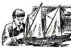
Is it possible to build an airplane on our own nowadays? Tver amateur aviators Yevgeny Ignatiev, Yuri Gulakov and Alexander Abramov answered this question in the affirmative, creating a winged single-seat machine, later called Argo-02. The plane turned out to be successful: it successfully flew at all-Union competitions, was the first winner of the regional review competition of amateur aircraft in Yaroslavl. The secret of Argo's increased popularity among amateur aviators is not in the design or technological refinements of the designers, but rather in their traditional character. The designers managed to achieve a successful combination of the design methods of wooden machines of the 1920s and 1930s, worked out over many decades, and modern aerodynamic calculations of aircraft of this class. This, perhaps, is one of the main advantages of the aircraft: its manufacture does not require modern plastics and composites, rolled products from high-strength metals and synthetic fabrics at all - only pine timber, a little plywood, canvas and enamel are needed.
However, the simplest design from common materials is just one of the components of the success of the machine. In order for all these pine slats and pieces of plywood to “fly”, they must be “fitted” into certain aerodynamic shapes. In this case, the authors of "Argo" - we must give them their due - showed an enviable design instinct. For their aircraft, they chose the aerodynamic design of a classic low-wing cantilever with a pulling propeller.
Today, against the background of a wide variety of "ducks", "tandems" and other miracles of modern aerodynamics, an aircraft of the "Argo" type even looks conservative. But this is precisely the wisdom of an aircraft designer: if you want to build a successfully flying aircraft, choose a classic scheme - it will never let you down.
However, this is not all. In order for an aircraft to fly well, it is necessary to correctly determine the ratio of its mass, engine power and wing area. And here the Argo parameters can be considered optimal for a device with a motor with a power of only 28 hp.
If someone wants to build such an aircraft, the Argo parameters can be taken as a model: it is their ratio that provides the best flight performance: speed, rate of climb, takeoff run, mileage, etc.
At the same time, the stability and controllability of an aircraft are determined by the ratio of the area of the wing, empennage and rudders, as well as their relative position. And in this area, as it turned out (which the Argo designers perfectly understood!), So far, no one has invented anything better than the standard classical scheme. Moreover, for the "Argo" the parameters are taken directly from the textbook: the area of the horizontal tail is 20% of the wing area, and the vertical - 10%; the tail arm is equal to 2.5 of the aerodynamic chord of the wing, and so on, without any deviation from the classical design rules, which obviously make no sense to deviate from.


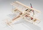
1 – screw spinner (gluing from fiberglass); 2- air propeller(plywood from pine); 3 - V-belt gearbox; 4 - engine type RMZ-640; 5 - subframe (pipes made of steel 30KhGSA); 6 - tachometer sensor; 7 - check valve; 8 - fire partition; 9 – the hatch of a mouth of a gas tank; 10 - compensator; 11 – fuel tank (aluminum sheet); 12 - instruments (navigation and piloting and engine operation control); 13 - visor (plexiglass); 14-engine carburetor throttle control handle (THROUT); 15 – control knob for roll and pitch; 16 - pilot's seat (pasted from fiberglass on an epoxy binder); 17 - chair back; 18 - block of rollers for wiring control cables; 19 – intermediate rocker of the Elevator; 20 – thrust of the Elevator; 21 - engine hood (gluing from fiberglass on an epoxy binder); 22 - fuel filter; 23 - motor mount attachment point; 24 - suspended control pedals along the course; 25 – mount of the spring chassis; 26 – chassis wheel 300×125 mm; 27 – chassis spring (steel 65G); 28 - filling syringe; 29 – control rod of the Elevator; 30 - fairing (gluing from fiberglass on an epoxy binder); 31 – intermediate rocker control the elevator; 32 - a block of rollers for rudder control cables; 33 – rudder control cable; 34 – control rod of the Elevator; 35 - a block of rollers for wiring cables for controlling the rudder; 36 – rudder drive lever; 37 – tail support (crutch)

1– control knob; 2– handle for controlling the throttle valve of the engine carburetor (THROD); 3 - THC; 4 - VR-10; 5 - EUP; 6 - US-250; 7 - VD-10; 8 - TE-45; 9 - shock absorber; 10-fuel tank; 11 – fire hydrant; 12 - control pedals on the course

1 – aircraft control stick for roll and pitch; 2 - throttle control handle of the engine carburetor (ORE); 3– rudder; 4– elevator; 5 – aileron; 6 - control pedals on the course
Although aerodynamic data allow the aircraft to perform aerobatics, however, aerial acrobatics is not only successful aerodynamics, but also high structural strength. According to the calculations of the authors and the technical commission, the operational overload at the Argo was equal to 3, which is quite enough for flights in a circle and short routes. Aerobatics is categorically contraindicated for this device.
Amateur aircraft designers should not forget about this ... On August 18, 1990, during a demonstration flight at a holiday dedicated to the Day of the Air Fleet, Yuri Gulakov introduced the Argo into another coup. This time, the speed turned out to be slightly higher than usual, and the maximum operational overload, obviously, far exceeded the calculated “troika”. As a result, the wing of the Argo disintegrated in the air, and the pilot died in front of the assembled spectators.
As a rule, such tragic cases, even with all the obviousness of the reasons that cause them, make us look for errors in the design of the aircraft and in the calculations. As for the Argo-02, the car withstood exactly as much as it was designed for. That is why the technical and flight methodological commissions for amateur-built aircraft of the Ministry aviation industry at one time, Argo-02 was recommended as a prototype for self-construction.
"Argo-02" is an ultra-light training cantilever low-plan of a classic wooden structure with a cantilever tail. The aircraft has a spring-type landing gear with a tail support.
Power point- two-stroke 2-cylinder air-cooled engine RMZ-640, which drives a two-blade wooden monoblock propeller through a V-belt gearbox. The aircraft control system is of the normal type. The cockpit is equipped with flight control instruments and engine operation control instruments.
The fuselage is wooden, of a cross-truss structure, with spars made of wooden slats with a section of 18 × 18 mm. Behind the cockpit, on top of the fuselage, there is a light fairing, the basis of which is foam plastic diaphragms and stringers. There is also a fairing in the front of the fuselage, in front of the cockpit it is made of wooden diaphragms and sheathing of sheet duralumin 0.5 mm thick. The cockpit and the tail section of the fuselage in the stabilizer attachment area are sheathed with plywood 2.5 mm thick. All other surfaces of the fuselage are fabric covered.
The spars of the center section pass through the cockpit, to which the pilot's seat molded from fiberglass and covered with artificial leather and the manual control post of the aircraft are attached.
The sides of the cabin are covered with foam plastic from the inside, and on top of it - with artificial leather. On the left side there is a throttle - a throttle control handle for the engine carburetor.
The dashboard is knocked out of sheet duralumin and covered with hammer enamel. In the cockpit, it is attached to frame No. 3 on shock absorbers. Devices are mounted on the board itself: TGC, US-250, VR-10, VD-10, EUP, TE and an ignition switch, a fuel valve under the board, and a filler syringe on the front side member. In front of the fuselage, under the fairing, a fuel tank with a capacity of 15 liters is fixed.
In the lower part of the fuselage, in front of the front spar, landing gear attachment points are installed. On the front frame, which is also a fire barrier, a lever-type pedal suspension unit and a roller and foot control fixation unit are mounted. On the other side of the fire wall there is a non-return valve, a fuel filter and a drain cock.
The attachment points of the motor mount are installed at the junctions of the spars with the front frame. The motor mount itself is welded from chromansile (steel 30GSA) pipes with a diameter of 22 × 1 mm. The engine is attached to the motor mount through rubber shock absorbers. The power plant is closed by the upper and lower fiberglass hoods. The propeller blank is glued from five pine plates with epoxy resin and, after final processing, covered with fiberglass using an epoxy binder.


The basis of each semi-wing is longitudinal and transverse sets. The first consists of two spars - the main and auxiliary (walls), frontal stringer and fins. The main spar is two-shelf, the upper and lower shelves are made of pine slats of variable section. So, the cross section of the upper shelf: at the wing root - 30 × 40 mm, and at the end - 10 × 40 mm; bottom - 20 × 40 mm and 10 × 40 mm, respectively. Diaphragms are installed between the shelves in the region of the ribs. The side member is sheathed with plywood 1 mm thick on both sides; in the root part - plywood 3 mm thick. In the root part of the wing and the attachment area of the aileron rocker, wooden bosses are fixed.
The nodes for docking the wing consoles with the center section are mounted in the root part of the wing on the front (main) spar. They are made of steel grade 30HGSA. At the end of the spar there is a mooring knot.
The frontal stringer of the wing frame is made of a wooden rail with a section of 10 × 16 mm, the tail stringer is made of a rail with a section of 10 × 30 mm.
From the toe to the front spar, the wing is sheathed with plywood 1 mm thick. A ladder is formed in the root part of plywood 4 mm thick.
The transverse set of the wing includes normal and reinforced ribs. The latter (ribs No. 1, No. 2 and No. 3) have a beam structure and consist of shelves with a section of 5 × 10 mm, racks and a plywood wall 1 mm thick with lightening holes. Normal ribs are trussed. They are assembled from shelves and braces with a section of 5 × 8 mm using scarves and knits. The wingtips are foam. After processing, they are pasted over with fiberglass on an epoxy binder.
Aileron - slotted type with a frame made of a spar with a section of 10 × 80 mm, ribs made of plates 5 mm thick, attack ribs and streamline ribs. The toe is sewn up with plywood 1 mm thick; together with the spar, the lining forms a rigid closed profile resembling a semicircular pipe. The aileron hinge units are mounted on the spar, and the reciprocal hinge brackets are mounted on the rear spar of the wing. All surfaces of the aileron and the wing itself are covered with canvas.
The horizontal tail of the aircraft "Argo-02" consists of a stabilizer and elevators. The stabilizer is two-spar, with diagonally arranged ribs, which provides it with high torsional rigidity. The toe to the front spar is sheathed with plywood 1 mm thick. The stabilizer can be operated both in a cantilever and in a strut version. The second option involves the installation of strut attachment points on the rear spar. The attachment points of the stabilizer to the fuselage are mounted on the front and rear spars. The elevator attachment points are located on the rear stabilizer spar; their design is similar to the arrangement of the nodes of the A-1 airframe. Styrofoam stabilizer ends, covered with fiberglass, central part lined with plywood.
The elevator is made of two parts, which to some extent duplicate each other. Each of the parts consists of a spar, obliquely placed ribs with socks and fins. The nose of the rudder is sheathed with plywood 1 mm thick. The elevator control horn is fixed in the root part.
The vertical tail of the aircraft is the keel and rudder. The keel is structurally made integral with the fuselage according to the two-spar scheme. Its frontal part (up to the front spar) is sheathed with plywood. The rear spar is a development of the rear fuselage frame.
The rudder is similar in design to the elevator or aileron. It also consists of a spar, straight and diagonal ribs and a streamline fin. The front part of the steering wheel up to the spar is covered with plywood. The hinge points are forked bolts. The control lever is fixed at the bottom of the spar. The strut attachment point is also mounted there. All plumage is covered with canvas.
The main landing gear of the aircraft is two-wheeled, spring type. The spring is curved from steel 65G; wheels with dimensions of 300 × 125 mm are attached to its ends. The spring is attached to the fuselage by a steel plate and a pair of bolts on each side, with which the spring is clamped and thus fixed relative to the fuselage.
The tail support is a 65G steel strip attached to the fuselage with two bolts, to which the support cup is screwed from below.

1 - carburetor; 2 - check valve; 3 - fuel filter; 4 - expendable capacity; 5 - tank plug with drainage; 6 – fuel tank; 7 - fire hydrant; 8 – power fitting; 9 - drain fitting; 10 - drain valve; 11 - filling syringe

1 – static pressure distributor; 2– durite hose; 3 - aluminum pipeline; 4 - air pressure receiver (PVD)
Elevator control is rigid, with the help of a handle (from the Yak-50 aircraft), duralumin rods and intermediate rocking chairs. Aileron control is also tight. The rudder drive is cable, with the help of suspended lever pedals, steel cables with a diameter of
3mm and textolite rollers with a diameter of 70 mm. To prevent foreign objects from entering the control units, the floor and the route of rods and cables are covered with a decorative screen.
The power plant of the aircraft is based on an engine of the RMZ-640 type, mounted on an engine mount in an inverted position - down by the cylinders. Above the engine is the upper pulley of the V-belt gearbox with a belt tensioning mechanism. Fiberglass hoods are screwed to self-locking anchor nuts on the fuselage and connecting ring.
The propeller is glued with pine-laminate epoxy and then patterned, covered with fiberglass and painted. The Argo-02 used several of these propellers with different diameters and pitches. One of the most acceptable in terms of its aerodynamic qualities has the following characteristics: diameter - 1450 mm, pitch - 850 mm, chord - 100 mm, static thrust - 85 kgf. The propeller spinner is glued from fiberglass on an epoxy binder and planted on a duralumin ring. Fastening the spinner to the propeller with screws.

The fuel system of the aircraft includes a fuel tank with a capacity of 14 liters, a fuel pump, a fuel filter, a non-return valve, a fire cock, a drain cock, a tee and a piping system.
The fuel tank is welded from 1.8 mm thick aluminum sheet. In the lower part there is a supply tank, into which the supply and drain fittings are welded, in the upper part there is a filler neck with drainage, inside there are communicating baffles to prevent fuel foaming. The tank is fixed on two beams with the help of tie-down bands with felt pads.
The system of air pressure receivers (APD) consists of an AP tube (from the Yak-18 aircraft) installed on the left wing plane, dynamic and static pressure tubes, connecting rubber hoses, a distributor and instruments.
Aircraft performance data
Length, m……………………………………………4.55
Height, m……………………………………………1.8
Wingspan, m…………………………………..6.3
Wing area, m2………………………………6.3
Narrowing of the wing………………………………………0
End chord of the wing, m……………………..1.0
MAR, m………………………………………………..1.0
Wing installation angle, hail…………………..4
Angle V, degrees…………………………………………..4
Sweep angle, deg…………………….0
Wing profile……………………….R-Sh 15.5%
Aileron area, m2………………………..0.375
Aileron span, m………………………………..1,5
Aileron deflection angles, degrees:
up…………………………………………………..25
down……………………………………………………….16
GO span, m……………………………………..1.86
GO area, m2…………………………………..1,2
Installation angle of GO, deg………………………..0
RV area, m2……………………………….0.642
VO area, m2…………………………………0.66
VO height, m………………………………………1.0
Area PH, m2…………………………………0.38
Deviation angle PH, deg…………………- 25
Deviation angle RV, deg………………….- 25
Fuselage width in the cockpit, m…………0.55
Fuselage height in the cockpit, m………….0.85
Chassis base, m………………………………………2.9
Chassis track, m……………………………………1.3
Engine:
type……………………………………………RMZ-640
power, hp………………………………………..28
Max. speed, rpm ………5500
Reducer:
type……………………………….. V-belt,
four-strand
gear ratio…………………………….0.5
belts, type…………………………………….A-710
Fuel………………………………..gasoline A-76
Oil…………………………………………..MS-20
Screw diameter, m…………………………………1.5
Screw pitch, m……………………………………..0.95
Static thrust, kgf……………………………95
Weight of the empty apparatus, kg…………………145
Maximum takeoff weight, kg………7235
Fuel reserve, l……………………………………15
Range
flight balances, % MAH…………24. ..27
Stall speed, km/h……………………72
Max. speed
horizontal flight, km/h……………..160
Maximum
piloting speed, km/h…………….190
Cruising speed, km/h…………………120
Breakaway speed, km/h………………………….80
Landing speed, km/h……………………70
Rate of climb near the ground, m/s………………2
Run, m……………………………………………….100
Mileage, m……………………………………………..80
Range
operational overloads…….+3..- 1.5
A. ABRAMOV, Tver
Noticed an error? Select it and click Ctrl+Enter to let us know.
Since 2005, Cetus Aero has been conducting master classes in the construction of aluminum aircraft. The fact is that since 2009 this company has been the official representative of the American company Van's Aircraft, the world leader in the production of aircraft for amateur construction. Since 1973, Van's Aircraft has produced 8000 assembly kits or whatever called "whales". Let's visit the company's assembly plant in Lukhovitsy and see how to build an aircraft ourselves, and is it really possible to do it at all?

If the saying “There are three capitals in Russia: St. Petersburg, Moscow and Lukhovitsy” can still be disputed or discussed, then the fact that Lukhovitsy is one of the centers of the aviation industry to date cannot be discussed. The Lukhovitsky Machine-Building Plant, which is now a branch of JSC RAC MiG, is still operating now, at a time when most similar industries have sheltered shops, clubs, fitness centers and other non-core assets on their territory. The production capacities of the Lukhovitsky branch of Cetus Aero can hardly compete with the machine plant, but more modest premises are enough for the production of aircraft with a wingspan of up to 10 meters. Moreover, these rooms are multifunctional and can even be transformed into a hall for a master class for 50 people. A feature of this room is that nothing needs to be taken out for this event: all the equipment and tools located along the walls temporarily become teaching aids for conducting a master class.


Even before the official start of the event, a relaxed dialogue began between the guests and representatives of the company: people come here with a ready-made package of questions.

San-Sanych, widely known in the Internet circles of aviation enthusiasts, who is also the head of the company, delivered an introductory speech. A short introductory word smoothly moved on to the first block of the master class: “Registration of Single Instances Aircraft and obtaining SLG EEVSE”. The topic is quite complex and very specific for different regions of Russia.

All Van's Aircraft aircraft, except for the RV-12, are equipped with power plants based on Lycoming engines. Cetus Aero is a certified center for assembling these boxer engines, which is why in the next block of the master class, Alexander dwelled in sufficient detail on the assembly features of these engines. Also very vigorously discussed the topic of the use of motor gasoline and the corresponding modifications of the engine - an urgent Russian theme for two reasons: the lack of domestically produced aviation gasoline in most of Russia and the high price of imported. We also discussed a very promising topic of aviation diesel engines. As it turns out, there are more questions than answers here.


In the next block of the master class, Nikolai focused on the installation of power supply systems and flight and navigation equipment. There is a certain feature here. If an aircraft airframe or a whale is a set of parts, assemblies and normals assembled in accordance with the specification of a specific aircraft modification, while only options with a tail and nose wheel are possible, then the set of flight and navigation equipment and elements of the aircraft electrical system is very specific. First, there is no set here. Secondly, components have a big difference in price. And thirdly, and most importantly, it is precisely in the configuration of these systems that the capabilities of the aircraft under construction and the individuality of the builder are manifested. Whoever wants, he assembles his dashboard in such a way, and from here - wires, terminals, connectors and switches and, as a result, the price. Nikolai dwelled in detail on the "aviation approach" to the selection of components and installation of systems: what can be used and what cannot.


Further, Anton dwelled on the technology of assembling airframes from aluminum alloys used in the manufacture of Van's Aircraft aircraft.
The basis of the design of Cetus aircraft in Russia and RV in America is an airframe or frame riveted from parts made of aluminum alloys. Most of the parts are made from semi-finished sheet products of different thicknesses. Extruded profiles and milled parts are also used. The aircraft also has welded assemblies made of chromoly steel: they are supplied welded and painted as part of the kit. All large and complex parts such as skins are cut to the so-called clean size and, in this case, nothing needs to be tried on and cut. Only a number of small details of a simple shape need to be cut out, and then only partially. The assembly technology of the units is applied by assembly holes, for this purpose all holes for fasteners are pre-made in all parts: rivets, screws and bolts.
Aluminum alloy for the manufacture of sheet parts is used with protective plating: coating with a thin layer of pure aluminum. The fact is that pure aluminum has rather low mechanical characteristics, but its corrosion resistance is very high. Aluminum alloys, on the other hand, have improved mechanical characteristics, but their corrosion resistance is significantly lower. Plating here is a compromise option: it is durable inside, but does not corrode on the outside. In turn, the top clad layer is quite soft and can be easily damaged. To this end, it is protected by a blue polyethylene film. Finally, the entire film is removed before the complete closure of the unit with casing.
I also want to note that the details of the most critical assembly units, such as the wing spar and power frames, are anodized as a protective coating. And it is easy to notice: the silvery surface is plating, and the yellow-orange one is anodizing.
Blind riveting is used on the outer surfaces, while in the case of a thin riveted package, riveting is used with the sheet stamped to fit the conical shape of the embedded rivet.


A workshop with the necessary machine park is equipped in a separate room.

Bending machine: some small parts in the kit need to be bent at an angle. This machine allows you to make high-quality parts: even along the entire length and without distortions.

Stationary hand punch for countersunk rivet punching on wide cladding panels.

The most basic hand tools always have their place.

And now let's take a closer look at the main tools that are used in the assembly of thin-walled riveted structures made of aluminum alloys.

In the center of the picture are typical stamped parts in a protective polyethylene film. On the right with a red handle is a thermal gun for cutting the protective film. Before riveting, cut off the part of the film that will be in contact with another part. More to the right is a syringe for sealant. When riveting fuel tanks, a three-component sealant of domestic production is used.


The oddly shaped pliers are one of the most important assembly tools used on Cetus aircraft. They are designed for setting cleco: special clamps, through which structures are pre-assembled.
Above - core. It would seem - a traditional tool for metalwork. Only this core with a secret. You don’t need to hit it with a hammer, for fear of rebound and inaccurate markings. Inside is a spring with adjustable compression. You just set it at the right point, squeeze it and the striker inside flies off, thus a point is outlined.
Multi-colored bent parts a little higher on the left are the key to a high-quality assembly of the entire aircraft. These are gauges that check the accuracy of the closing heads of rivets.
Next - drills with drilling depth limiters and a special tool for pulling the skins when the holes do not match. This is necessary for this: in the delivery, the skins are flat, but on the plane they are cylindrical and conical, so not all the holes can match right away, because the skin is also springy.

In plastic disposable cups that are used for tea and coffee, these are the same glue: they differ in the color of the body material - for different hole diameters. Above on the right is a riveting gun for impact riveting. Left: various heads, including curved ones - for riveting in hard-to-reach places.

A special gauge or template for selecting bolts by diameter and length is a convenient tool for assembly.

Parallelogram sliding template allows easy and precise marking of the rivet seam.

Two round fixtures are designed to bend (edge) the edge of thin-walled skin for a tighter fit to the elements of the inner set.

In the middle of the picture on the left - conductors for installing anchor nuts. Further, various stamps for performing under-stamping of the skin when setting countersunk rivets. Squisser or pneumatic punching tool. With a blue handle - a simple and convenient tool for deburring the edge of a drilled hole. Electric drill (former screwdriver). Pneumatic drill. Manual punching pliers. And a set for making a metal tool box is wrapped in paper - a task for those who will be on the second day of the master class.

The next block of the master class is devoted to the manufacture of parts from composite materials. Although the aircraft is all-metal, it still uses parts made of fiberglass, namely non-power structures with double curvature. These on the aircraft are: hoods, landing gear fairings, wheel fairings, wingtips and fairings. Andrey conducted this part of the master class, and he invited the future builder Maxim to help. The subject of their work was the fairing, which is installed between the spring fairing of the main landing gear and the wheel fairing. Technology, like the previous ones, requiring a certain skill and skill.


Then Gennady spoke, who came from Novosibirsk and shared with everyone the experience of real self-construction. It should be noted that in his story he paid more attention not to the technical aspects of aircraft construction, but to the organizational process as a whole and revealed a number of important points.

In conclusion, two workplaces were organized for practical study of the technological process of riveting thin-walled aluminum structures.


As you can see, the master class consisted of separate blocks, after which breaks were organized with unlimited opportunities for tea drinking, coffee drinking, and also liver eating! And everyone was given a very tasty homemade lunch of borscht and pilaf. Well, tea and coffee in the afternoon were also unlimited. As for the cost. Lunch - 250 rubles, the first day of the master class - free of charge, the second (Sunday) provided for an individual workplace - (set for riveting an individual tool box + workplace with tools + instructor) cost 5500 rubles.

Many thanks to Elena for the overall organization of the event, professional answers to legal questions and, in general, pleasant communication!

25 people were pre-registered for the master class. Is it a lot or a little? Considering that the first such event took place 9 years ago and many of the enthusiasts have already visited it and are successfully building aircraft, especially in our difficult times, I think it's normal. Moreover, the procedure itself was more like not a lecture, but a practical dialogue. It was easy to ask a question on the topic right from the spot, and company representatives were always willing to adjust their answers in accordance with the needs of the listeners.
How can such a seminar help all those present? Perhaps the most important thing that such lively practical communication gives is that it allows you to open up to aviation enthusiasts the whole range of issues related to the independent construction of an aircraft:
1. Motivation. Building an aircraft, especially on your own, is a rather lengthy process. It may drag on for years. And all this time, the aircraft builder must ask himself the question: why do I need all this? Do I like it all? And if you even think for a second, it is better not to start at all. Especially a decrease in motivation can occur after several years of construction, when the result of labor as an integral product is not yet visible.
2. Project financing. The advantage of building an aircraft from a whale (or a kit) is that it saves on the wages of assembly workers, and it is also possible, with proper planning, to distribute costs: what to pay now and what in a year. For example, an engine, which sometimes costs the same as the cost of a whole set of aircraft airframes, can be bought later. I would like to dispel one myth that by purchasing a kit for assembling an aircraft, you have fulfilled the main costs. In fact, the price of a whale is, at best, 35% of the total cost of building an aircraft, and this is important to understand from the very beginning.
3. Responsibility to others. This phrase is not mine. This important point in his story was touched by Gennady from Novosibirsk. Every builder has a family. And only when family members become full-fledged assistants in the assembly of the aircraft, when they are imbued with the spirit of independent aviation construction, only then will success be achieved.
4. Construction site. There is an opinion that an aircraft can also be built in a garage. Garage is different for a garage: a standard room with a size of 6x3 m will not allow even the fuselage of a classic two-seater aircraft to be assembled here. To perform the docking of all units, especially the leveling, a room of this size is clearly not enough. It will be hard for the builder who, having started building, will notice this later and begin to rebuild the garage and turn it into a full-fledged hangar.
5. "Additional" work. Starting to build an aircraft from the frame assembly, the aviation enthusiast thinks that he is doing the bulk of the work. Of course, this is the basis of all construction. But there is more: the power plant, electrics and flight and navigation complex, painting and finishing. Unlike the frame, which has a complete set of parts, there are no standard sets for all of the above works. For each specific project, depending on financial capabilities, it is necessary to draw up a specification for the equipment to be installed, then select the appropriate fittings, and then assemble it all! All this is transformed from standard work into classic tuning. Involvement of external contractors for the quality performance of these works can increase the cost of the project as a whole.
6. Registration and legal support of the project. If you are building a plane to avoid flying around the tail, you must register with the EEAF to be able to legally fly, and not chain the plane to the ground for the rest of its life.
7. Flights, storage and operation. It's also a good idea to answer these questions before construction starts, so you don't have to transport the assembled aircraft thousands of miles for a single flight. And ground storage in our difficult climatic conditions and the provision of fuel and lubricants in general is a topic for a separate discussion, which goes beyond the boundaries of my story.
There are a lot of questions, and some of them can't be answered right away. But there is a dream of flying and a desire to create, build an Airplane with your own hands. Isn't this the main engine and the main motivation of the whole process? And everyone you see sitting in this hall is overwhelmed with precisely these thoughts. Let's wish good luck in all their endeavors and thank Cetus Aero for the excellently prepared and professionally conducted next Master Class!!!

Homemade aircraft, drawings of machines and a brief description of them built by amateur designers
PHOENIX M-5

A model that is equipped with two Vikhr-25 motors modified for air cooling. The design of the handle and the control scheme of the machine have no analogues in the world. Eminent test pilots did not hide their delight, and even recommended its use on military fighters.
The take-off weight of the machine is two hundred and fifty-five kilograms, and the wing surface area is five point six square meters.
VOLKSPLAN

The model was designed by an amateur American designer, with a pulling screw, which consists of the following units:
Shaft (1), made of duralumin pipe
fuselage spar (2), the material of which is made - pine
hull sheathing (3), made of plywood 3 mm thick
wing spars (4)
arc (5)
tank (6) that holds thirty liters of fuel
frame (7), made of plywood thirty millimeters thick
automobile engine (8), the power of which is sixty horsepower
hood (9), made of fiberglass
spring (10)
technological holes for installing wings (11)
wing braces (12)
his racks (13)
his braces (14)
strut bolt (15)
Specifications:
Takeoff weight is three hundred and forty kilograms
the wing area is nine point twenty-nine tenths of a square meter
speed - one hundred and seventy kilometers per hour
This model passed certification tests and was found fit for use, moreover, it was possible to perform aerobatics and even a “corkscrew” on it.
AGRO-02

Created by Tver designers. The main material used in its manufacture is plywood, canvas, pine and the domestic RMZ-640 engine. The take-off weight of which was two hundred and thirty-five kilograms and the wing area was six point three tenths of a square meter.
KhAI-40

Designed by students of the Kharkov Aviation Institute. The model has a beam fuselage.
SINGLE-SEAT BI-PLANES


SINGLE BEAM AIRCRAFT
Probably every adult in our country knows how to make an airplane out of paper. After all, this unpretentious toy, originally from childhood, invariably delights and delights with its ability to fly. Before the dominance of tablets and other gadgets, it was ordinary paper airplanes that pleased boys of all ages at recess.
And how many schemes for collecting this toy do you know? Do you know that from an ordinary sheet of A4 paper, you can add a lot of various kinds aircraft, including long and far flying, as well as military models?
Are you already intrigued? You can start folding airplanes right now. After all, for this you need only paper, desire, a little patience and our schemes. Let's fly!
The simplest schemes of the basic aircraft model
Before proceeding to complex models, let's brush up on the basics of aircraft construction. We bring to your attention 2 of the most simple ways fold the plane.Using the first scheme, it is easy to get a universal aircraft familiar from childhood. It does not differ in special takeoff and landing characteristics, but it will not be difficult even for a child to fold it. And an adult will cope with the assembly in just a minute.

Even if the first scheme seemed too complicated for you, use the simplified method. It allows you to get the desired result as quickly as possible.

He's on the video:
A plane that flies for a long time
The dream of any child is a long-flying airplane. And now we will help you make it a reality. According to the diagram provided, you can fold the model, which is distinguished by the duration of the flight.Remember that flight performance is affected by the dimensions of your aircraft.
Excess weight, which means the length of the wings, prevents the aircraft from flying. That is, a glider aircraft must have short, wide wings. Another friend of planning is the absolute symmetry of the model.
You need to throw it not forward, but up. In this case, it will stay in the sky for a long time, smoothly descending from a height.

Look for answers to the remaining questions and all the subtleties of folding a paper glider in a step-by-step video tutorial.
Plans for fast flight
Interested in participating in a model aircraft competition? They are easy to arrange at home. Just fold high-speed planes out of paper - and you can set your own records.
Step-by-step following our photo instructions is the key to success. A number of general recommendations will also help novice paper aviation enthusiasts.
- To improve flight performance, use only a completely flat sheet of paper. Ideal for ordinary office printers. Any bruises and folds repeatedly worsen the aerodynamic properties of the model.
- Iron all the folds with a ruler to make them clearer.
- Pointy aircraft nose increases his speed, but at the same time range decreases flight.

Ready-made crafts can be painted with children. This exciting activity will allow you to turn a folded piece of paper into a real attack aircraft or an unusual fighter.
Approach building your models like a science experiment. The speed and ease of assembly of origami airplanes allow you to analyze their flight and make the necessary changes to the design.

Be sure to check out the video master classes for creating fast paper planes to avoid annoying mistakes and learn from someone else's experience.
Paper long-range fighter
Describing this model aircraft, many enthusiastically promise that it will be able to fly 100 meters, and call it a super-aircraft. At the same time, they are absolutely not embarrassed that the officially registered record for the flight range of a paper airplane is only 69 m 14 cm.
However, doubts are gone. In any case, such a cool handsome man is worthy of your efforts to create it. For this craft, stock up on a sheet of A4 paper (you can take thick colored paper to make the airplane as beautiful as possible), unlimited patience and accuracy. If your goal is a realistic fighter, assemble it slowly and follow the photo instructions step by step.
Also at your service is a video from which you will learn how to correctly assemble a paper fighter plane that stays in the air for a long time.
A model with stable flight
A paper airplane takes off and immediately starts to fall, or instead of a straight trajectory, it writes out arcs. Are you familiar with this?Even this children's toy has certain aerodynamic properties. This means that it is the duty of all novice aircraft builders to approach the design of a paper model with full responsibility.
We suggest you fold another cool airplane. Thanks to the blunt nose and wide deltoid wings, it will not go into a tailspin, but will please you with a beautiful flight.

Do you want to master all the subtleties of building this glider? Check out the detailed and accessible video tutorial. After a powerful charge of inspiration, you will definitely want to fold an airplane with your own hands, which will flutter like a bird.
Cornflower plane - an original craft for young aircraft modellers
Do you have a boy growing up who already loves to craft, glue and cut something? Give him a little time - and together you can make a small mock-up of a corn plane. It will surely bring a lot of joy: first from joint creativity, and then from fun with a toy made by oneself.
For work, you will need the following improvised materials:
- colored paper;
- double-sided colored cardboard;
- Matchbox;
- scissors;
- PVA glue.
First of all, glue the matchbox with colored or white paper. Cut a strip of cardboard 3 cm wide. Half of its length will correspond to the length of the aircraft fuselage. Fold the strip in half and glue it to the box.

Cut out two identical rounded wings, their width should be slightly larger than the width of the box.
Glue the wings to the plane. This can be entrusted to a little helper, he will be happy with such an important mission and will do everything well and carefully. Cut and glue a rectangle on the front to hide the box.

Cut out two elongated ovals for the tail of the plane and a strip for the vertical piece. It needs to be folded as shown in the photo.

Glue the blanks to the tail of the maize. The resulting cardboard masterpiece remains to be decorated according to your desire. You can glue stars or small pictures to it. A good addition would be a propeller made of thin strips of paper.

Such a wonderful plane can be taken to the kindergarten as a craft or please dad on February 23.
Video bonuses
Do you want to get a plane that can not only take off high, but also return back to your hands? Think it can't be? And here you are wrong.Tireless craftsmen-experimenters have developed a scheme for an amazing aircraft - boomerang.
With it, you can show your friends a stunning trick: a launched airplane will obediently fall right into your hands every time. To be known as the master of paper planes, check out our video - you will definitely succeed.
It would seem that all samples of paper planes have already been reviewed and tested in practice, but we still have something to surprise you with. We invite you to watch a video tutorial on creating a realistic glider.
You don't even need origami folding skills, you just cut out the outline from paper. This model has excellent flight characteristics, and the whole secret lies in ... ordinary plasticine. Watch the video, be surprised and surprise.
Creating various paper planes is not only a wonderful activity that allows you to drive away boredom and put off the ubiquitous gadgets. It develops intelligence, accuracy and fine motor skills of hands. That is why it is so useful to include this type of activity in the program of joint leisure with children.
Perhaps the first unsightly model will be your child's first step towards a serious passion for aircraft modeling. And it is in your family that a brilliant designer will grow up passenger liners or new jet fighters. Everything can be. It makes no sense to look far into the future, but devoting an hour or two to folding paper airplanes is definitely worth it.
You decide to build an airplane. And immediately before you the first problem - what should he be? Single or double? Most often, this depends on the power of the existing engine, the availability of the necessary materials and tools, as well as the size of the "hangar" for building and storing the aircraft. And in most cases, the designer has to opt for a single-seat training aircraft.
According to statistics, this class of aircraft is the most massive and popular among amateur designers. For such machines, a variety of schemes, types of structures and engines are used. Equally common are biplanes, low-wing and high-wing monoplanes, single- and twin-engine, with pulling and pushing propellers, etc.
The proposed series of articles contains an analysis of the advantages and disadvantages of the main aerodynamic schemes of aircraft and their design solutions, which will allow readers to independently evaluate the strengths and weak sides various amateur designs, will help you choose the best one and the most suitable for construction.
WITH AIRCRAFT - ONE TO ONE
One of the most common schemes for an amateur single-seat aircraft is a strut-braced monoplane with a high wing and a tractor propeller. It should be noted that this scheme appeared in the 1920s and has not changed much over the entire period of its existence, becoming one of the most studied, tested and constructively worked out. The characteristic features of an aircraft of this type are a wooden two-spar wing, a welded steel truss fuselage, linen sheathing, a pyramidal landing gear and a closed cockpit with an automobile-type door.
In the 1920s - 1930s, a variation of this scheme became widespread - an aircraft of the "parasol" type (from the French parasol - an umbrella from the sun), which was a high-wing aircraft with a wing fixed on racks and struts above the fuselage. "Parasols" in amateur aircraft construction are still found today, however, as a rule, they are structurally complex, less aerodynamically perfect and less convenient to operate than classic high-wing aircraft. In addition, such devices (especially small ones) have very difficult access to the cabin and, as a result, the difficulty of its emergency escape.


Single-seat high-wing aircraft:
Engine - LK-2 with a power of 30 hp. designs L. Komarov, wing area - 7.8 m2, wing profile - Clark, take-off weight - 220 kg (pilot - 85 kg, power plant - 32.2 kg, fuselage - 27 kg, landing gear with skis -10.5 kg , horizontal tail - 5.75 kg, wing with struts - 33 kg), maximum speed - 130 km / h, flight range with a fuel reserve of 10 l-180-200 km
Engine - Zündapp with a power of 50 hp, wing area - 9.43 m2, take-off weight - 380 kg, empty weight - 260 kg, maximum speed -150 km / h, rate of climb near the ground - 2.6 m / s , flight duration -8 h, stall speed - 70 km/h

The advantages of high-wing aircraft include the simplicity of piloting technique, especially if the specific load on the wing does not exceed 30 - 40 kg / m2. High-wing aircraft are distinguished by good stability, excellent takeoff and landing characteristics, they allow rear centering up to 35-40% of the mean aerodynamic chord (MAC). From the cockpit of such an apparatus, the pilot is provided with an optimal downward view. In short, for those who are building their first aircraft, and besides, they are going to master its piloting on their own, the best scheme do not invent.
In our country, amateur aircraft designers have repeatedly turned to the scheme of a strut high-wing aircraft. So, at one time a whole squadron of “parasol” aircraft appeared: “Kid” from Chelyabinsk, created by the former pilot L. Komarov, “Leningradets” from St. .Frolov from the village of Donino near Moscow.
The last device should be told in more detail. Having well studied the simplest scheme of a high-wing strut, the designer carefully planned his work. The wing was made of pine and plywood, the fuselage was welded from steel pipes and these elements of the aircraft were covered with canvas according to classical aviation technology. I chose large wheels for the landing gear so that I could fly from unprepared unpaved grounds. The power unit is based on a 32-horsepower MT-8 engine, equipped with a gearbox and a large-diameter propeller. Aircraft takeoff weight - 270 kg, flight centering - 30% MAR, specific wing load - 28 kg / m2, wing span - 8000 mm, propeller thrust in place - 85 kgf, maximum speed - 130 km / h, landing speed - 50 km /h
Test pilot V. Zabolotsky, who flew around this device, was delighted with its capabilities. According to the pilot, even a child can control it. The aircraft was operated by V. Frolov for more than ten years and participated in several ULA rallies.
The PMK-3 aircraft, created in the city of Zhukovsky near Moscow by a group of amateur aircraft designers led by N. Prokopts, caused no less delight among the test pilots. The car had a peculiar forward fuselage, a very low landing gear and was designed according to the scheme of a strutted high-wing aircraft with a closed cockpit; a door was provided on the left side of the fuselage. The wing is slightly beveled back to provide the necessary centering. The design of the aircraft is solid wood, covered with fabric. The wing is single-spar, with pine shelves, a set of ribs and a wing forehead are sheathed with plywood.

Wing area - 10.4 m2, wing profile - R-Sh, takeoff weight - 200 kg, fuel capacity - 13 l, flight centering - 27% MAH, static propeller thrust - 60 kgf, stall speed - 40 km / h, maximum speed - 100 km / h, flight range - 100 km
The basis of the fuselage - three spars, and therefore the fuselage had a triangular cross section. The plumage and control system of the PMK-3 aircraft are made as in the well-known training glider B. Oshkinis BRO-11 M. The basis of the power plant is a 30-horsepower liquid-cooled outboard motor "Vikhr"; while the radiator protruded slightly from the starboard side of the fuselage.
An interesting variety of amateur-built strutted high-wing aircraft was the Don Quixote, developed in Poland by J. Yanovsky. With the light hand of an amateur aircraft industry enthusiast, a well-known glider test pilot and journalist G.S. Malinovsky, who published the drawings of Don Quixote in the Modeler-Konstruktor magazine, this, in general, not entirely successful scheme, was very widespread in our country - at times there were more than four dozen similar devices at ALS rallies. True, professional aircraft designers believe that amateur aviators in this scheme were attracted primarily by the unusual appearance of the aircraft, but it was in it that some “pitfalls” lurked.
A characteristic feature of the "Don Quixote" was the forward cockpit, which provided excellent visibility and comfortable accommodation for the pilot. However, on an extremely light aircraft weighing up to 300 kg, the balance changed significantly when a more slender pilot, weighing 60 kg, sat in the cockpit instead of an 80-kg pilot - while the device suddenly turned from excessively stable into absolutely unstable. It was necessary to avoid such a situation even when designing the machine - it was only necessary to install the pilot's seat in the center of its gravity.


Aircraft with a pusher propeller, designed according to the scheme of the Don Quixote aircraft:
Engine power - 25 hp, wing area - 7.5 m2, empty weight - 150 kg, takeoff weight - 270 kg, maximum speed - 130 km / h, rate of climb near the ground - 2.5 m / s, ceiling - 3000 m, flight range - 250 km. Machine structure - solid wood
Engine power - 30 hp, wing span -7 m, wing area - 7 m2, empty weight - 105 kg, takeoff weight - 235 kg, maximum speed - 160 km / h, rate of climb - 3 m / s, flight duration - 3 h
Construction - fiberglass, engine power - 35 hp, wing span - 8 m, wing area - 8 m2, wing profile - Clark YH, takeoff weight - 246 kg, empty weight - 143 kg, flight centering - 20% MAR, maximum speed - 130 km/h
Another feature of the Don Quixote is the tailwheel landing gear. As is known, such a scheme, in principle, does not ensure the directional stability of a light aircraft when it moves along the airfield. The fact is that with a decrease in its mass and moments of inertia, the movements of an aircraft become fast, sharp, short-term, and the pilot has to concentrate all his attention on maintaining the direction of the takeoff or run.
The A-12 aircraft from the Aeroprakt club (Samara), which was one of the copies of Don Quixote, had exactly the same birth defect as the first-born of this galaxy, but the designers, after testing the machine by professional pilots V. Makagonov and M Molchanyuk quickly found an error in the design. By replacing the tail wheel with a nose wheel on the A-12, they completely eliminated one of the main drawbacks of the Polish aircraft.
Another significant drawback of Don Quixote is the use of a pusher propeller, shaded in flight by the cockpit and wing. At the same time, the efficiency of the propeller dropped sharply, and the wing, which was not blown by the air flow from the propeller, did not provide the calculated lift. As a result, takeoff and landing speeds increased, which led to a lengthening of the takeoff run and run, and also reduced the rate of climb. With a low thrust-to-weight ratio, the aircraft could not take off from the ground at all. This is exactly what happened at one of the ALS rallies with the Elf aircraft, built according to the Don Quixote scheme by students and employees of the Moscow Aviation Institute.
Of course, it is not forbidden to build devices with a pusher propeller, however, the need and expediency of creating an aircraft with such a power plant in each specific case should be carefully evaluated, since losses in thrust and wing lift are inevitable.
It should be noted that designers who creatively approached the use of a power plant with a pusher propeller managed to overcome the shortcomings of such a scheme and create very interesting options. In particular, several successful devices according to the Don Quixote scheme were built by a machine operator from the city of Dneprodzerzhinsk P. Atyomov.

Wing area - 8 m2, takeoff weight - 215 kg, maximum speed - 150 km/h, stall speed - 60 km/h, rate of climb near the ground - 1.5 m/s, operating overload range - from +6 to -4

1 - metal toe of the wing; 2 - tubular spar of the wing; 3 - flap; 4 - tubular spars of the aileron and flap; 5 - aileron; 6 - engine control handle; 7 - entrance door of the cockpit (right); 8 - engine; 9 - aileron control rod; 10 - brace in the plane of the wing; 11 - riveted duralumin fuselage beam; 12 - tubular spars; 13 - speed indicator; 14 - ignition switch; 15 - altimeter; 16 - variometer; 17 - slip indicator; 18 - cylinder head temperature gauge; 19 - flap control knob; 20 - dorsal parachute
A well-flying aircraft with a pusher propeller was created by a team of amateur aircraft designers from the Flight Club of the Samara Aviation Plant under the leadership of P. Apmurzin - this machine was called the Crystal. Test pilot V. Gorbunov, who flew around it, did not stint on high marks - according to his reviews, the car had good stability, was light and easy to operate. Samarans managed to ensure high efficiency of the flaps, deviated by 20° on takeoff and 60° during landing. True, the rate of climb of this aircraft was only 1.5 m / s due to the shading of the pusher propeller by the wide cockpit. Nevertheless, the named parameter turned out to be quite sufficient for an amateur design - and this despite the fact that its takeoff was somewhat difficult.
The attractive appearance of the "Crystal" is combined with the excellent production performance of an all-metal monoplane. The airframe fuselage is a duralumin beam riveted from 1 mm D16T sheets. The power set of the beam also included several walls and frames curved from sheet duralumin.
It should be noted that in amateur designs, instead of metal, it is quite possible to use plywood, pine bars, plastics and other available materials.
In the bend of the fuselage beam, in its bow, there was a cockpit, covered with a large transparent faceted lantern and a light fairing made of sheet D16T 0.5 mm thick.
The strut wing is of an original single-spar design with a spar made of a 90x1.5 mm duralumin tube, which takes loads from bending and torsion of the wing. A set of ribs made of 0.5 mm D16T, stamped into rubber, was fixed to the spar with rivets. The wing brace is made of 50x1 duralumin tube and ennobled with a D16T fairing. In principle, duralumin spars and struts can be replaced with wooden, box-section ones.
The wing was equipped with ailerons and flaps with a mechanical manual drive. Wing profile - Р-ІІІ. The aileron and flap had spars made of duralumin tubes with a diameter of 30x1 mm. Wing forehead - from 0.5 mm sheet D16T. The surfaces of the wing were covered with canvas.
Plumage - free-bearing. The keel, stabilizer, rudder and elevator are also single-spar, with spars made of D16T pipes with a diameter of 50x1.5 mm. The plumage was covered with linen. The aileron control wiring had rigid rods and rocking chairs, the wiring to the rudders was cable.
Chassis - tricycle, with a steerable nose wheel. Depreciation of the landing gear on the aircraft occurred due to the elasticity of pneumatic wheels with dimensions of 255x110 mm.
The basis of the power plant of the aircraft is a 35-horsepower two-cylinder engine RMZ-640 from the Buran snowmobile. The propeller is of wooden construction.
When comparing pulling and pushing propellers, it must be borne in mind that for vehicles with a low power of the power plant, the first is more efficient, which at one time was superbly demonstrated by the French aircraft designer Michel Colomban, an employee of the Aerospasial company, the creator of a small and very elegant Cri-Cri aircraft. "(cricket).
It will not be superfluous to recall that the creation of small-sized aircraft with engines of minimum power has attracted both amateurs and professionals at all times. Yes, constructor big planes O.K. Antonov, who has already built the flying giant An-22 "Antey" with a take-off weight of 225 tons, in his book "Ten Times First" spoke about his old dream - a tiny aircraft with an engine of 16 hp. Unfortunately, Oleg Konstantinovich did not have time to create such an apparatus ...
Designing a compact aircraft is not as easy as it might seem at first glance. Many conceived it as an ultralight machine with extremely low wing loading. As a result, ultra-light devices were obtained that could fly only in the complete absence of wind.
Later, designers came up with the idea of using wings of a small area and with a large specific load for such vehicles, which made it possible to significantly reduce the size of the machine and increase its aerodynamic quality.


Twin-engine low-wings:
B - the plane "Pasya" by Edward Magransky (Poland) is a good example of the creative development of the "Kri-Kri" scheme:
Power plant - two KFM-107E engines with a total power of 50 hp, wing area - 3.5 m2, wing aspect ratio - 14.4, empty weight - 180 kg; takeoff weight - 310 kg; maximum speed - 260 km / h; stall speed - 105 km / h; flight range - 1000 km

1 - air pressure receiver of the speed indicator; 2 - duralumin propeller (maximum rotational speed - 1000 rpm); 3 - Rowena engine (cylinder displacement 137 cm3, power 8 hp, weight 6.5 kg); 4 - resonant exhaust pipe; 5 - membrane carburetor; 6 - fuel intakes - flexible hoses with weights at the ends (one per engine); 7 - gas sector (left side); 8 - the handle of the trim effect mechanism (reconfiguring the spring loader of the elevator); 9 - discharged part of the lantern; 10 - unsupported rocking chair in cable wiring for rudder control; 11 - hard wiring control stabilizer; 12 - cable wiring of the rudder drive; 13 - all-moving horizontal tail; 14 - rocking rudder; 15 - keel spar; 16 - chassis in the compressed position of the damping; 17 - main chassis spring; 18 - drain tube of the fuel tank; 19 - aileron-flap hover control knob (left side); 20 - fuel tank with a capacity of 32 l; 21 - cable wiring for controlling the nose landing gear; 22 - adjustable pedals; 23 - pedal loader (rubber shock absorber); 24-rubber shock absorber right landing gear; 25 - engine installation frame (steel V-shaped pipe); 26 - bow control rocker; 27 - wing spar; 28 - hovering aileron (deviation angles from -15° to +8°, hovering - +30°; 29 - foam frame; 30 - wing skin; 31 - hanging aileron mounting bracket; 32 - foam ribs; 33 - stabilizer tip (balsa ); 34 - stabilizer spar; 35 - toe of the aileron (sheathing - duralumin, filler - foam)