This is a light aircraft single-engine double monoplane-parasol of the classical scheme with a steerable tail wheel. Designed for training flights.
The aircraft wing has a TsAGI RI profile with a relative thickness of 14%. Technologically, the wing is divided into a center section and consoles. The center section is attached to the fuselage with four struts (a pair of front ones with struts). Racks are made of a pipe (steel 20) with a diameter of 36x1 mm, struts - from the same pipe, only with a diameter of 25x1 mm. The consoles are connected to the center section and with the help of struts - to the fuselage.
Wing struts - oval profile and section 100x40 mm glued from four pine plates with different directions of transverse fibers (plywood). At the console there is a spar made of a duralumin pipe with a diameter of 110 mm and a wall thickness of 2 mm (from an irrigation system), and at the center section it is made of a steel pipe with a diameter of 40 mm and a wall thickness of 1.5 mm. In the places where the wing struts are attached, the spars of the consoles are reinforced with bougie - bushings 700 mm long and with an outer diameter corresponding to the inner diameter of the spar tube.
At the ends of the bougie, wedges are cut for about 200 mm for a more even distribution of the load. Subsequently, to ensure the required margin of longitudinal stability, the centering of the aircraft was shifted forward relative to the average aerodynamic chord, giving the wing consoles a sweep angle. For this, steel fork ears with overlays had to be riveted to the root end of the console spar. The fastening of the center section to the struts, and the struts to the fuselage, as well as the wing components, was carried out with M8 bolts.
The ribs are wooden. They were assembled mainly from lime slats with a section of 6x6 mm (upper and lower arms, struts). The bow of the wing toe is made of the same bent rail of variable section. Knits - from 1 mm plywood, and the rack of the spar - from 3 mm plywood. Each rib is strung on the spar pipe through a hole in the rack and attached to it with four duralumin corner brackets with rivets.
In places where the wing struts are attached to the spar, as well as the racks of the end and root ribs, they are riveted at eight points. Here I also note that the root ribs are reinforced, their arches and struts are made of rails with a section of 12x6 mm. In the bow, along the entire console, the ribs are connected by three stringers: lower, front (middle) and upper.
Between the ribs, from the front stringer to the top, additional semi-arcs made of 3 mm plywood are installed. The rear wall of the wing console is channel-shaped, wooden, consists of two shelves (bars with a section of 15x15 mm) and a wall (1-mm plywood) used to hang ailerons and flaps.
The toe of the wing from the lower stringer to the upper to ensure the rigidity of the profile is sheathed with 1 mm plywood, and the rest of the bearing surface is covered with calico fabric sewn to the power and shaping elements of the wing consoles with threads.
The canvas is impregnated with homemade enamel - a solution of celluloid in acetone. At the points of attachment to the wing of the struts, in the consoles between the spar and the rear wall, struts are installed, made in the likeness of the latter: the wall is made of 3 mm plywood, and the shelf is made of slats with a section of 15x10 mm. The aileron ribs and flaps are made of lime plates with cutouts for lightening, while the spars are made of 12x12mm pine shelves and 1mm plywood walls.
The toes of the ailerons and flaps up to the spars are sheathed with 1 mm plywood. The assembly of parts of the ribs of the entire wing and fuselage was carried out on epoxy glue - a binder that has been repeatedly tested in practice. Wing covering - linen (coarse calico), impregnated with enamel. The fuselage is wooden, truss structure, rectangular section. The basis of its power set are four pine spars with a section in the front and middle parts of 20x20 mm and turning into a section of 16x16 mm - in the tail section. The spars are connected to each other in a farm by means of racks and crossbars of the same section.
The nose and tail parts of the fuselage are sheathed with 3 mm plywood. The middle part is complemented by braces and covered with calico. Tail plumage - wooden with braces. The stabilizer consists of a spar and a rear wall with ribs between them and is sheathed with a fabric impregnated with enamel. An elevator consisting of two halves is hung on the rear wall. The nose of the rudder up to the spar is covered with 1 mm plywood (like a wing), which takes up torsional loads, and the rest of the surface is covered with an impregnated fabric.
Vertical tail: keel and rudder are made similar to the horizontal tail. The rudder control is cable, and the elevator is mixed. The chassis is pyramidal with the main wheels from the Tula scooter. The main landing gear is made of pipes with a diameter of 36x1.5 mm, they are pivotally connected to the lower fuselage spars through four corner brackets. Shock absorbers - spring. The tail support is controlled, with a rubber lamellar shock absorber and a wheel with dimensions of 200x80 mm.
The motor frame is welded from pipes (steel 20) with a section of 20x2 mm and fastened to the fuselage spars through four brackets-pads. The engine is joined to it at four points through silent blocks. As a power unit in the propeller installation, an engine from a VAZ-21083 car was used, and without alterations, only a muffler from a Minsk motorcycle was fitted to its exhaust manifold.
Torque from the engine air propeller transmitted through a homemade gear reducer with a gear ratio of 2.6. The drive gear (27 teeth) is from the Izh-Planet-Sport motorcycle, the driven gear (70 teeth) is home-made, their shafts are machined from the gearbox shaft of the GAZ-51 truck.
The gearbox housing is welded from a 3 mm steel sheet and machined using simple fixtures on school lathes and milling machines. The fuel tank with a capacity of 50 liters is located in the forward fuselage. Propeller with a diameter of 1.6 m - pulling, monoblock two-bladed, wooden (re-glued from pine bars), covered with two layers of fiberglass on an epoxy binder, with brass sheet edging. Subsequently, it was replaced by a similar one, but with a diameter of 2 m. At the same time, it was necessary to increase the height of the propeller axis, which was achieved by narrowing the chassis track. The propeller develops 150 kgf thrust in takeoff mode.
Controls and instruments are mounted in both cabins. Aircraft control (elevator and ailerons) - from any of the two handles connected by a rod and located in front of the seats in each of the cockpits. The deflection of the rudder and the turn of the tail wheel are made simultaneously from the pedals by means of cable wiring. Engine control - from the lever, fixed to the left of the pilot. The flaps are controlled by a lever handle with a latch from the pilot's seat from the rear cockpit.
The aircraft is equipped with instruments that control the operation of the engine and ensure flight in simple meteorological conditions. All of them are located on the dashboards in both cockpits. The seats are self-made, equipped with seat belts - car seat belts. The aircraft passed the technical commission and was registered with the FLA in 2002. To date, his flight time has exceeded 500 hours (2412 landings).
After 500 flight hours, the engine was revised. Wear of rubbing parts has not yet been detected. During operation, changes were made to the design of the aircraft, although not cardinal. So, over time, the cable control of the ailerons was replaced by a rigid one. For the cockpits, instead of sides, for the convenience of the pilot and passenger, hinged doors were made on one side. Changed the design of the tail support and the location of the pedals.
The wheels of the main supports were equipped with mechanical brakes driven by a lever on the handle through a cable in a Bowden braid. Transparent visors made of 5 mm plexiglass were installed in front of the cockpits, a headrest for the pilot, and a small trunk was organized behind the back of the seat in the rear cockpit. Reinforced stabilizer mount front strut.
Changed the color of the plane. At the end of May 2008, our team with the "Persistent" aircraft once again participated in the All-Russian Gathering of Aviation Fans in Vladimir. Annual flights to and from the rally have shown that the aircraft is capable of covering distances of several hundred kilometers without landing. I advise amateur aircraft designers: build simple planes more boldly. They are available to everyone. Just be persistent and confident in yourself, and then you will succeed! Good luck!
General characteristics of the aircraft:
Take-off weight, kg .............................................. ................600
Empty weight, kg .............................................. .................435
Fuel reserve, l ............................................... ......................70
Speed, km/h:
detachment .............................................. ...................................60
boarding ................................................. .........................40
cruising .............................................. .....................100
maximum ................................................. .................140
stalling ................................................. .........................40
Rate of climb, m / s .............................................. .............3
Run / run, m .............................................. ................70/100
Wing
Span, m ............................................... ...............................10.75
Area, m2............................................... ............................15
Chord, m ............................................... .................................1.4
Profile................................................. ............... R-P-14%
Angle of installation, hail .............................................. ................3
Angle of transverse V deg .............................................. ......1.5
Sweep angle along the leading edge, degrees .............................. 2
Aileron span, m ............................................... ...................2
Aileron chord, m ............................................... .................0.35
Aileron deflection angles, deg...................................+30/-2
Flap span, m ............................................... ................2.5
Flap chord, m ............................................... ................0.35
Flap deflection angle, deg ..............................................15
Base, m ............................................... .................................4.05
Track, m ............................................... ................................1.85
The size of the main wheels, mm ............................................... 440x100
Tail wheel size, mm .............................. 185x45
Span of the stabilizer, m ............................................... .......3.1
Stabilizer root chord, m.......................................1.08
Stabilizer area, m2 ............................................... 2.85
Angle of installation of the stabilizer, hail ....................................-1
Elevator chord, m ............................................... .............0.5
Elevator area, m2 ............................................... .....1.45
Elevator deflection angles, deg .........................+30/-25
vertical tail
Keel height, m ............................................... ...................1.36
Keel area, m2 ............................................... .................1.38
Rudder area, m2 .........................................0.88
Rudder deflection angles, deg.................+30/-30
Power point
Engine................................................. ............... VAZ-21083
Type................................................. .................carbureted
Max, RPM ............................................................... 5500
Max, power, hp .............................................. ...................70
Operating modes (power / rpm):
Take-off (operating time - up to 5 minutes) ..................... 56/4700
nominal................................................. ............49/4100
cruising................................................. .............43/3600
small “gas” .............................................. .................24/2000
Fuel brand .................................................. ... AI-92, AI-93
Double aircraft monoplane-parasol "Persistent": 1 propeller; 2-reducer; 3-engine hood; 4 - wing struts; 5 - visor (2 pcs.); 6 cabins (2 pcs.); 7-gargrot; 8-fuselage; 9- keel; 10-rudder; 11-tail wheel; 12-tail support with a wheel; 13-main landing gear; 14-wheel of the main landing gear (from a scooter, 2 pcs.); 15-muffler (from the Minsk motorcycle); 16-wing console (2 pcs.); 17 - overlay (duralumin, sheet s 1, 2 pcs.); 18 - wing center section; 19-strut of the wing console (2 pcs.); 20-spacer (duralumin pipe with a diameter of 20, 4 pcs.); 21-flap (2 pcs.); 22-aileron (2 pcs.); 23 stabilizer; 24-rudder

Wing console: 1-spar (duralumin tube D16T with a diameter of 110x2); 2-root rib (pine lath 12x6); 3- sheathing of the root part (plywood s1); 4- normal rib (pine lath 6x6); 5-half-arc (plywood s3); 6-bracing (pipe D16T, 045, 2 pcs.); 7-spacer with a bracket (pine rail 6x6, plywood s1, 2 pcs.); 8-front (middle) stringer (triangular pine rail, a = 10); 9-lower and upper stringers (pine rail s12x8); 10-rack spar (plywood s3); 11-back wall (pine slats 15x15 and 25x25, plywood s1); 12 - toe lining (plywood s1); 13-terminal rib (pine rail 12x6); 14 - filler (polystyrene,); 15 - ending; 16-strut of the aileron rib and flap (8 pcs.); 17-unit suspension aileron to the console; 18-sock aileron (plywood s1); 19-spar aileron (pine rail 10x10, plywood s 1); 20-rib of the aileron (linden plate s1); 21 - trailing edge of the aileron; 22-transverse aileron control rod (duralumin tube with a diameter of 8); 23 rocking chair; 24 longitudinal aileron control rod (duralumin tube with a diameter of 10); 25-top bow (pine rail 6x6); 26-lower rib bow (pine rail 6x6); 27-braces (pine rail 6x6); 28-knit (plywood s1); 29-bougie of the spar (duralumin tube with a diameter of 113x1.5); 30-corner bracket; 31-bracket mounting bracket; 32-eye fork (front assembly) for attaching the console to the center section (steel, sheet s2.2 pcs.); 33 - spars of the center section (steel pipe with a diameter of 40x1.5), furnishings; 34 rear wall spacer (pine rail 15x15, according to the number of ribs); 35-strut aileron spar or flap (pine rail 10x10, according to the number of ribs); 36-bracket (rear assembly) for attaching the console to the center section; 37-bracket for quick coupling of the flap with its control lever


Horizontal plumage: 1 - stabilizer spar (pine bar-plywood 40x35); 2-stabilizer rib (linden plate s 6); 3 - rear wall of the stabilizer (pine bar 30x10); 4-toe elevator (plywood s 1); 5-spar of the elevator (pine block-plywood 40x30); 6-rib of the steering wheel (linden plate s 6); 7-rear edge of the elevator (pine bar 30x10); 8-knit (plywood s 1); 9-horn control the elevator (steel 20, sheet s 2); 10 - brackets for fastening the brace and braces (steel 20, sheet s 2); 11 - elevator suspension unit to the stabilizer (2 pcs.); 12-tail part of the aircraft fuselage

Motor mount and its attachment points to the fuselage: 1-motor mount (steel pipe with a diameter of 20); 2 - silent block (from the Zhiguli car, 4 pcs.); 3-bracket (steel, sheet s4, 4 pcs.); 4-fuselage

Chassis: A-main supports; B-tail support

Mounting points: A-wing consoles to the center section; B-stabilizer to the rear of the fuselage and the hinge of the elevator on the stabilizer; B-flap control lever; G-rudder and tail wheel


Aircraft control schemes: A - ailerons. Initial version: mixed - from cable wiring and rigid rods; B-flaps; In-elevator; G-rudder and tail wheel.

Cabin equipment - dashboard and controls: 1-engine control lever (ORE); 2-aircraft control stick (RUS); 3-toggle switch ignition; 4-electronic tachometer; 5-complex device for monitoring engine operation parameters; 6 - generator failure indicator; 7 - turn and slip indicator; 8 - altimeter; 9-speed indicator; 10-variometer; 11 o'clock; 12 - engine start button; 13-pedal lever (2 pcs.); 14 - pocket for a portable radio station; 15 seat; 16 - seat belts


Aircraft landing gear: a-main rack; b-tail support
 Is it possible to build an airplane on our own nowadays? Tver amateur aviators Yevgeny Ignatiev, Yuri Gulakov and Alexander Abramov answered this question in the affirmative, creating a winged single-seat machine, later called Argo-02. The plane turned out to be successful: it successfully flew at all-Union competitions, was the first winner of the regional review competition of amateur aircraft in Yaroslavl. The secret of Argo's increased popularity among amateur aviators is not in the design or technological refinements of the designers, but rather in their traditional character. The designers managed to achieve a successful combination of the design methods of wooden machines of the 1920s and 1930s, worked out over many decades, and modern aerodynamic calculations of aircraft of this class. This, perhaps, is one of the main advantages of the aircraft: its manufacture does not require modern plastics and composites, rolled products from high-strength metals and synthetic fabrics at all - only pine timber, a little plywood, canvas and enamel are needed.
However, the simplest design from common materials is just one of the components of the success of the machine. In order for all these pine slats and pieces of plywood to “fly”, they must be “fitted” into certain aerodynamic shapes. In this case, the authors of "Argo" - we must give them their due - showed an enviable design instinct. For their aircraft, they chose the aerodynamic design of a classic low-wing cantilever with a pulling propeller.
Today, against the background of a wide variety of "ducks", "tandems" and other miracles of modern aerodynamics, an aircraft of the "Argo" type even looks conservative. But this is precisely the wisdom of an aircraft designer: if you want to build a successfully flying aircraft, choose a classic scheme - it will never let you down.
However, this is not all. In order for an aircraft to fly well, it is necessary to correctly determine the ratio of its mass, engine power and wing area. And here the Argo parameters can be considered optimal for a device with a motor with a power of only 28 hp.
If someone wants to build such an aircraft, the Argo parameters can be taken as a model: it is their ratio that provides the best flight performance: speed, rate of climb, takeoff run, mileage, etc.
At the same time, the stability and controllability of an aircraft are determined by the ratio of the area of the wing, empennage and rudders, as well as their relative position. And in this area, as it turned out (which the Argo designers perfectly understood!), So far, no one has invented anything better than the standard classical scheme. Moreover, for the "Argo" the parameters are taken directly from the textbook: the area of the horizontal tail is 20% of the wing area, and the vertical - 10%; the tail arm is equal to 2.5 of the aerodynamic chord of the wing, and so on, without any deviation from the classical design rules, which obviously make no sense to deviate from.


1 – screw spinner (gluing from fiberglass); 2 - propeller (plywood from pine); 3 - V-belt gearbox; 4 - engine type RMZ-640; 5 - subframe (pipes made of steel 30KhGSA); 6 - tachometer sensor; 7 - check valve; 8 - fire partition; 9 – the hatch of a mouth of a gas tank; 10 - compensator; 11 – fuel tank (aluminum sheet); 12 - instruments (navigation and piloting and engine operation control); 13 - visor (plexiglass); 14-engine carburetor throttle control handle (THROUT); 15 – control knob for roll and pitch; 16 - pilot's seat (pasted from fiberglass on an epoxy binder); 17 - chair back; 18 - block of rollers for wiring control cables; 19 – intermediate rocker of the Elevator; 20 – thrust of the Elevator; 21 - engine hood (gluing from fiberglass on an epoxy binder); 22 - fuel filter; 23 - motor mount attachment point; 24 - suspended control pedals along the course; 25 – mount of the spring chassis; 26 – chassis wheel 300×125 mm; 27 – chassis spring (steel 65G); 28 - filling syringe; 29 – control rod of the Elevator; 30 - fairing (gluing from fiberglass on an epoxy binder); 31 – intermediate rocker control the elevator; 32 - a block of rollers for rudder control cables; 33 – rudder control cable; 34 – control rod of the Elevator; 35 - a block of rollers for wiring cables for controlling the rudder; 36 – rudder drive lever; 37 – tail support (crutch)

1– control knob; 2– handle for controlling the throttle valve of the engine carburetor (THROD); 3 - THC; 4 - VR-10; 5 - EUP; 6 - US-250; 7 - VD-10; 8 - TE-45; 9 - shock absorber; 10-fuel tank; 11 – fire hydrant; 12 - control pedals on the course

1 – aircraft control stick for roll and pitch; 2 - throttle control handle of the engine carburetor (ORE); 3– rudder; 4– elevator; 5 – aileron; 6 - control pedals on the course
Although aerodynamic data allow the aircraft to perform aerobatics, however, aerial acrobatics is not only successful aerodynamics, but also high structural strength. According to the calculations of the authors and the technical commission, the operational overload at the Argo was equal to 3, which is quite enough for flights in a circle and short routes. Aerobatics is categorically contraindicated for this device.
Amateur aircraft designers should not forget about this ... On August 18, 1990, during a demonstration flight at a holiday dedicated to the Day of the Air Fleet, Yuri Gulakov introduced the Argo into another coup. This time, the speed turned out to be slightly higher than usual, and the maximum operational overload, obviously, far exceeded the calculated “troika”. As a result, the wing of the Argo disintegrated in the air, and the pilot died in front of the assembled spectators.
As a rule, such tragic cases, even with all the obviousness of the reasons that cause them, make us look for errors in the design of the aircraft and in the calculations. As for the Argo-02, the car withstood exactly as much as it was designed for. That is why the technical and flight methodical commissions for aircraft amateur built Ministry aviation industry at one time, Argo-02 was recommended as a prototype for self-construction.
"Argo-02" is an ultra-light training cantilever low-plan of a classic wooden structure with a cantilever tail. The aircraft has a spring-type landing gear with a tail support.
The power plant is a two-stroke 2-cylinder air-cooled engine RMZ-640, which drives a two-blade wooden monoblock propeller through a V-belt gearbox. The aircraft control system is of the normal type. The cockpit is equipped with flight control instruments and engine operation control instruments.
The fuselage is wooden, of a cross-truss structure, with spars made of wooden slats with a section of 18 × 18 mm. Behind the cockpit, on top of the fuselage, there is a light fairing, the basis of which is foam plastic diaphragms and stringers. There is also a fairing in the front of the fuselage, in front of the cockpit it is made of wooden diaphragms and sheathing of sheet duralumin 0.5 mm thick. The cockpit and the tail section of the fuselage in the stabilizer attachment area are sheathed with plywood 2.5 mm thick. All other surfaces of the fuselage are fabric covered.
The spars of the center section pass through the cockpit, to which the pilot's seat molded from fiberglass and covered with artificial leather and the manual control post of the aircraft are attached.
The sides of the cabin are covered with foam plastic from the inside, and on top of it - with artificial leather. On the left side there is a throttle - a throttle control handle for the engine carburetor.
The dashboard is knocked out of sheet duralumin and covered with hammer enamel. In the cockpit, it is attached to frame No. 3 on shock absorbers. Devices are mounted on the board itself: TGC, US-250, VR-10, VD-10, EUP, TE and an ignition switch, a fuel valve under the board, and a filler syringe on the front side member. In front of the fuselage, under the fairing, a fuel tank with a capacity of 15 liters is fixed.
In the lower part of the fuselage, in front of the front spar, landing gear attachment points are installed. On the front frame, which is also a fire barrier, a lever-type pedal suspension unit and a roller and foot control fixation unit are mounted. On the other side of the fire wall there is a non-return valve, a fuel filter and a drain cock.
The attachment points of the motor mount are installed at the junctions of the spars with the front frame. The motor mount itself is welded from chromansile (steel 30GSA) pipes with a diameter of 22 × 1 mm. The engine is attached to the motor mount through rubber shock absorbers. The power plant is closed by the upper and lower fiberglass hoods. The propeller blank is glued from five pine plates with epoxy resin and, after final processing, covered with fiberglass using an epoxy binder.


The basis of each semi-wing is longitudinal and transverse sets. The first consists of two spars - the main and auxiliary (walls), frontal stringer and fins. The main spar is two-shelf, the upper and lower shelves are made of pine slats of variable section. So, the cross section of the upper shelf: at the wing root - 30 × 40 mm, and at the end - 10 × 40 mm; bottom - 20 × 40 mm and 10 × 40 mm, respectively. Diaphragms are installed between the shelves in the region of the ribs. The side member is sheathed with plywood 1 mm thick on both sides; in the root part - plywood 3 mm thick. In the root part of the wing and the attachment area of the aileron rocker, wooden bosses are fixed.
The nodes for docking the wing consoles with the center section are mounted in the root part of the wing on the front (main) spar. They are made of steel grade 30HGSA. At the end of the spar there is a mooring knot.
The frontal stringer of the wing frame is made of a wooden rail with a section of 10 × 16 mm, the tail stringer is made of a rail with a section of 10 × 30 mm.
From the toe to the front spar, the wing is sheathed with plywood 1 mm thick. A ladder is formed in the root part of plywood 4 mm thick.
The transverse set of the wing includes normal and reinforced ribs. The latter (ribs No. 1, No. 2 and No. 3) have a beam structure and consist of shelves with a section of 5 × 10 mm, racks and a plywood wall 1 mm thick with lightening holes. Normal ribs are trussed. They are assembled from shelves and braces with a section of 5 × 8 mm using scarves and knits. The wingtips are foam. After processing, they are pasted over with fiberglass on an epoxy binder.
Aileron - slotted type with a frame made of a spar with a section of 10 × 80 mm, ribs made of plates 5 mm thick, attack ribs and streamline ribs. The toe is sewn up with plywood 1 mm thick; together with the spar, the lining forms a rigid closed profile resembling a semicircular pipe. The aileron hinge units are mounted on the spar, and the reciprocal hinge brackets are mounted on the rear spar of the wing. All surfaces of the aileron and the wing itself are covered with canvas.
The horizontal tail of the aircraft "Argo-02" consists of a stabilizer and elevators. The stabilizer is two-spar, with diagonally arranged ribs, which provides it with high torsional rigidity. The toe to the front spar is sheathed with plywood 1 mm thick. The stabilizer can be operated both in a cantilever and in a strut version. The second option involves the installation of strut attachment points on the rear spar. The attachment points of the stabilizer to the fuselage are mounted on the front and rear spars. The elevator attachment points are located on the rear stabilizer spar; their design is similar to the arrangement of the nodes of the A-1 airframe. The ends of the stabilizer are foam plastic, pasted over with fiberglass, the central part is sheathed with plywood.
The elevator is made of two parts, which to some extent duplicate each other. Each of the parts consists of a spar, obliquely placed ribs with socks and fins. The nose of the rudder is sheathed with plywood 1 mm thick. The elevator control horn is fixed in the root part.
The vertical tail of the aircraft is the keel and rudder. The keel is structurally made integral with the fuselage according to the two-spar scheme. Its frontal part (up to the front spar) is sheathed with plywood. The rear spar is a development of the rear fuselage frame.
The rudder is similar in design to the elevator or aileron. It also consists of a spar, straight and diagonal ribs and a streamline fin. The front part of the steering wheel up to the spar is covered with plywood. The hinge points are forked bolts. The control lever is fixed at the bottom of the spar. The strut attachment point is also mounted there. All plumage is covered with canvas.
The main landing gear of the aircraft is two-wheeled, spring type. The spring is curved from steel 65G; wheels with dimensions of 300 × 125 mm are attached to its ends. The spring is attached to the fuselage by a steel plate and a pair of bolts on each side, with which the spring is clamped and thus fixed relative to the fuselage.
The tail support is a 65G steel strip attached to the fuselage with two bolts, to which the support cup is screwed from below.

1 - carburetor; 2 - check valve; 3 - fuel filter; 4 - expendable capacity; 5 - tank plug with drainage; 6 – fuel tank; 7 - fire hydrant; 8 – power fitting; 9 - drain fitting; 10 - drain valve; 11 - filling syringe

1 – static pressure distributor; 2– durite hose; 3 - aluminum pipeline; 4 - air pressure receiver (PVD)
Elevator control is rigid, with the help of a handle (from the Yak-50 aircraft), duralumin rods and intermediate rocking chairs. Aileron control is also tight. The rudder drive is cable, with the help of suspended lever pedals, steel cables with a diameter of
3mm and textolite rollers with a diameter of 70 mm. To prevent foreign objects from entering the control units, the floor and the route of rods and cables are covered with a decorative screen.
The power plant of the aircraft is based on an engine of the RMZ-640 type, mounted on an engine mount in an inverted position - down by the cylinders. Above the engine is the upper pulley of the V-belt gearbox with a belt tensioning mechanism. Fiberglass hoods are screwed to self-locking anchor nuts on the fuselage and connecting ring.
The propeller is glued with pine-laminate epoxy and then patterned, covered with fiberglass and painted. The Argo-02 used several of these propellers with different diameters and pitches. One of the most acceptable in terms of its aerodynamic qualities has the following characteristics: diameter - 1450 mm, pitch - 850 mm, chord - 100 mm, static thrust - 85 kgf. The propeller spinner is glued from fiberglass on an epoxy binder and planted on a duralumin ring. Fastening the spinner to the propeller with screws.

The fuel system of the aircraft includes a fuel tank with a capacity of 14 liters, a fuel pump, a fuel filter, a non-return valve, a fire cock, a drain cock, a tee and a piping system.
The fuel tank is welded from 1.8 mm thick aluminum sheet. In the lower part there is a supply tank, into which the supply and drain fittings are welded, in the upper part there is a filler neck with drainage, inside there are communicating baffles to prevent fuel foaming. The tank is fixed on two beams with the help of tie-down bands with felt pads.
The system of air pressure receivers (APD) consists of an AP tube (from the Yak-18 aircraft) installed on the left wing plane, dynamic and static pressure tubes, connecting rubber hoses, a distributor and instruments.
Aircraft performance data
Length, m……………………………………………4.55
Height, m……………………………………………1.8
Wingspan, m…………………………………..6.3
Wing area, m2………………………………6.3
Narrowing of the wing………………………………………0
End chord of the wing, m……………………..1.0
MAR, m………………………………………………..1.0
Wing installation angle, hail…………………..4
Angle V, degrees…………………………………………..4
Sweep angle, deg…………………….0
Wing profile……………………….R-Sh 15.5%
Aileron area, m2………………………..0.375
Aileron span, m………………………………..1,5
Aileron deflection angles, degrees:
up…………………………………………………..25
down……………………………………………………….16
GO span, m……………………………………..1.86
GO area, m2…………………………………..1,2
Installation angle of GO, deg………………………..0
RV area, m2……………………………….0.642
VO area, m2…………………………………0.66
VO height, m………………………………………1.0
Area PH, m2…………………………………0.38
Deviation angle PH, deg…………………- 25
Deviation angle RV, deg………………….- 25
Fuselage width in the cockpit, m…………0.55
Fuselage height in the cockpit, m………….0.85
Chassis base, m………………………………………2.9
Chassis track, m……………………………………1.3
Engine:
type……………………………………………RMZ-640
power, hp………………………………………..28
Max. speed, rpm ………5500
Reducer:
type……………………………….. V-belt,
four-strand
gear ratio…………………………….0.5
belts, type…………………………………….A-710
Fuel………………………………..gasoline A-76
Oil…………………………………………..MS-20
Screw diameter, m…………………………………1.5
Screw pitch, m……………………………………..0.95
Static thrust, kgf……………………………95
Weight of the empty apparatus, kg…………………145
Maximum takeoff weight, kg………7235
Fuel reserve, l……………………………………15
Range
flight balances, % MAH…………24. ..27
Stall speed, km/h……………………72
Max. speed
horizontal flight, km/h……………..160
Maximum
piloting speed, km/h…………….190
Cruising speed, km/h…………………120
Breakaway speed, km/h………………………….80
Landing speed, km/h……………………70
Rate of climb near the ground, m/s………………2
Run, m……………………………………………….100
Mileage, m……………………………………………..80
Range
operational overloads…….+3..- 1.5
A. ABRAMOV, Tver
Noticed an error? Select it and click Ctrl+Enter to let us know.
Good day everyone! How are you guys and girls? In the last article, we did it with you, and in this one we will make the plane of your dreams))). True, it will be made of paper, but such that it flies fast and far and no one can catch it.
And then you can arrange a competition and let all the paper planes rush to the distillation, how do you like this idea? Probably just great, because spring is coming soon, and there will be summer, when there will be much more fun and entertainment than now.
Everyone knows this toy, even kids, who also love and willingly sit and fold A4 sheets with great interest to get a wonderful craft and at the same time a flying machine above the ground.
The easiest way is familiar to all of us from childhood, absolutely everyone remembers it, both moms and your dads. Take a look at this picture.

First of all, we will make such an airplane that flies far, the main thing is that it flies straight and beautiful. Just what you need to have fun and be able to watch him))).
We will need:
- A4 sheet - 1 pc.
Stages of work:
1. Take a sheet, our toy will be made from it. Decide on the color, you can take a traditional white sheet, or you can take, for example, green or blue.

2. Lay the paper horizontally in front of you and fold it in half. We will do it using the origami technique.

3. Then open and rotate vertically. Begin to bend to a straight line.

4. Thus, at the top you get a triangle.

5. Now fold the resulting line back to the outside. Do this on both sides.

6. Repeat the steps again.

7. This is what should happen.

8. Then open all folded parts.

9. Fold the paper on both sides, where you have two marked lines to the center strip.

10. At the intersections, fold the sheet of paper forward.

11. Press the line with your fingers.

12. Open and return the sheet to its original position.

13. After bending along the first top line.

14. Fold to the center horizontal line.

15. Place the resulting corner exactly on the line.

16. Then turn the sheet over and fold along a horizontal line.

17. Turn the sheet over again to the other side and make the triangle look up.

18. Bend the tops central line when you start doing this, the product will begin to assemble.

19. Therefore, you have to push the paper very carefully with your own hands.

20. You need to do these actions from two sides.


21. Fold in half in half.

22. Bend the airplane's wings.

23. After, on the wings themselves, make folds of 1-1.5 cm.

24. Open the airplane and align your wings. Here is such a handsome man turned out, and ready to fly. Look, just don't fly too far))).

Origami paper plane in 5 minutes
For the smallest fidgets, there is of course a simpler instruction, such souvenirs turn out just as well and they also fly very well, depending on how you launch, you can not catch up and fly away hoo as 100 meters, you are tormented to look for later).

Most importantly, you need to make the two sides the same in the mirror image so that they turn out to be even and then everything will work out for sure.
On one of the forums, I looked at a craft called Piranha, and it looks like the truth? Also, the author chose the color red. See how cleverly you can turn such a miracle. No special skills are required. The most primitive version with a simple model.

It turned out to be a cool little thing, my boys really liked it).

By the way, you can get a little creative and give dad a little surprise.

In general, do such a craft with your child so that there is something to do in the circle of your beloved family, because such work is very close.

Step-by-step instructions for a flying toy for beginners
It is interesting that almost any aircraft can fly a sufficient number of meters above the ground, it can be 10,000 and even more than 1,000,000, the most important condition is, depending on what height it will be launched from and whether there will be wind outside and how it will pick it up.
If you want your airplane to never fall over, then use this scheme. Such a toy will show you a uniform and very fast flight. You yourself will be very surprised.

If you like such air transport with big wings, then fold this kind of airplane.

You can also build with a blunt nose, there will be no collisions for this.

Well, if you don’t understand diagrams and instructions at all, then watch this step-by-step video from the YouTube channel:
How to make a paper plane that will fly very far up to 10,000 meters?
In fact, there are quite a few a large number of various paper models of this air transport. Leading on this moment became the Hawk, Owl, Falcon and Albatross.
And this is not all to say, I propose to lay down a powerful and beautiful airplane called Thunderstorm.
Stages of work:
1. Be sure to bend a sheet of paper symmetrically, spread the resulting line very well with your hands, then turn it back.

2. Make a triangle at the top, as we did in the first example.

3. Bend the leaf to the center again on both sides, you get a sharp triangle.

4. Then bend the sheet where the fold point formed.


6. Next, roll the triangle forward again.

7. Turn over the resulting masterpiece and bend again.

8. Bend the plane in half. Bend the top of the wings a little, as shown in the photo.

9. And then bend so that you get real ones, like an airplane.

10. Voila, and that's what happened, it looks cool and cool, but how it cages, well, it's definitely fast and far).

DIY paper airplane model for kids with folding patterns
Do you want to make a bunch of beautiful and pretty sharp or blunt-nosed airplanes with your kids?
First of all, learn how to make these yourself, and then teach your little helpers this easy task. Start with the simplest model.
If you do not understand this scheme, go to the next one and choose.

We make a Glider from an A4 sheet easily and simply
If you want another look, which is obtained in a matter of minutes, and it will not be necessary to fold and bend much, a completely different technique is used. It turns out cool and original. In general, a cool option for a child who will gladly launch it in the air.
We will need:
- paper
Cooking method:
1. Bend sheet A4 in half and draw a line well with your hands. Take scissors or a clerical knife and cut along it.

2. You will get two small leaves, fold one sheet in half again and draw a blank with a pencil, which you can ask me for free, and then print it on your printer.

3. Cut out the template and don't forget to make gaps on the wings and tail as shown in the picture I sent you.


5. Take your time, iron the lines neatly and evenly.

6. There is no need to hurry, otherwise it will turn out to be a blunder.

7. Put a piece of plasticine into the nose of the air transport and close it.

8. Where the cuts were made on the tail, bend and straighten the paper.

9. Do the same with the wings.

10. To give flying ability, you need to smooth out the wings with a pencil and wrap them up a little.

11. It should turn out something like this. To test the elevator, lower the plane vertically down, it should take off like the wind, but don't overdo it.

If your plane tends to one of their sides, then adjust it, because you can lower or raise the traffic controllers.
Volumetric cardboard craft
We will need:
- cardboard - 2 sheets
- PVA glue
- ruler
- pencil
- scissors
- Matchbox

Stages of work:
1. Mark two strips on cardboard with a pencil, their width should be equal to a matchbox.

2. Then cut them out with scissors. From these strips make the wings of the plane. On another sheet, mark two strips 1.5 cm wide and also cut them along the length of the cardboard.

Move one such thin strip aside, and cut the second into two parts of 8 cm each, remove the rest, it will not be needed. Here's what happens:

3. Now start building. Take a matchbox, bend a long thin strip in half and attach, glue it to the box.

4. With the help of two identical strips that are wide, like boxes, make wings.

The corners can be rounded, cut them with scissors.
5. From one short narrow strip, make a tail and also round it, glue it inward. And glue the second one on top, make a triangle out of it.

6. After you can cut the propeller and glue it.

7. The craft is ready, enjoy your work!

Video on how to roll a Fighter without glue

Of course, it will be difficult to do such a craft if you are doing it for the first time, so I suggest starting by watching a video that will definitely teach you how to create such a charm.
Well, how did it work out for you? Is it really easy and simple and also without glue, and not difficult, as at first glance?
And if you have problems with the Internet, then you can always use the scheme, especially if you suddenly forget something, too, as an option.


P.S. By the way, craftsmen even make such airplanes from one match, see for yourself:
Well, that's all I have. I wish you creative success and good luck! Create for health, play and rejoice! All the best and joyful. Bye everyone!
Introduction
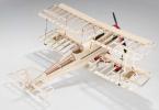
I was pushed to create my first aircraft by a banal lack of money and a desire to learn how to fly. Since the Chinese plane given to me by my girlfriend was repaired an endless number of times and, in the end, it became unrepairable, and there was not enough money to buy a new one, it was decided to build our own. Moreover, on the forum of the modelsworld.ru store, I was advised to do just that. Initially, I tried to copy the fuselage of my Chinese aircraft, but the construction of the aircraft requires at least some initial knowledge. Therefore, it is better to have at hand a manual already written by a more experienced designer. And, while still crawling on the Internet in search of a suitable aircraft, I came across an article "ParkFlyer 2 or our answer to Piper" and Cessn "e" by the author Evgeny Rybkin (link). A very successful option for me: high-wing, which means it is easier and more predictable to manage; I am also pleased that the aircraft is domestic, since our aircraft are practically not represented in this class.
I read the article, and although there is a slightly different manufacturing method, I decided to build according to this guide. True, if we compare both options, then only the name of the aircraft will be common - after all, Evgeny Rybkin's description is more suitable for those who already have experience in building models and have the necessary materials and tools. In a way, my example looks like "building an aircraft in unfavorable conditions." Therefore, the models also differ externally (Evgeny Rybkin's Yak-12 aircraft is on the left, My version of the Yak-12 aircraft is on the right):


The construction of my aircraft was carried out more intuitively than according to science: no calculations were made, no engine was selected, but what was available was stuck in. The remoteness of the city in which I live affects - more than 100 km to the only model store known to me, and in our construction stores it is a whole problem to buy a normal ceiling and good glue. Therefore, the construction process was constantly hampered by the lack of necessary materials and parts. As a result, something was taken from a crashed Chinese plane, something (and this is a large part) was invented from improvised material.
Since this is my first self-built aircraft, there were some mistakes. Therefore, in the process of creating the aircraft, it was necessary to look for different options for solving problems, then some corrections and upgrades appeared in the process. Therefore, it makes sense to read the article to the end, so as not to repeat my mistakes.
I would like to add that this article should not be taken as a guide to action or instructions for building an aircraft, as I, for example, took the article by E. Rybkin. It only describes the process of making a park flyer by a beginner, in the field of aircraft construction, practically from improvised means. But, if you are building your first aircraft, and you do not have the opportunity to get hold of branded parts, then, I hope, some points will be useful to you. In general, go for it, and everything will work out for you!
Materials and tools
In principle, it took me not so much material for this plane. Considering that some components and parts were reworked several times, trying to achieve a more accurate match, the amount of materials used is minimal. I spent most of my time, because due to work I could only fly in the evenings.
The article by E. Rybkin describes the production of an aircraft from PS-60 foam. There, a special machine is used to cut it, where a heated nichrome (maybe I'm wrong in the name) wire plays the role of a knife. Due to the lack of this fixture, I decided to make a model entirely from the ceiling. I had no more accessible material at that time. I used the ceiling of different manufacturers, different colors, but the same parameters: 500 * 500 mm, the same density, 3 mm thick and must look like a "box from Doshirak". The plane took me nine sheets. When shopping for ceiling tiles, buy a bottle of ceiling tile adhesive. I used glue "Master". As it turned out later, this is an analogue of the well-known glue "Titan". In general, ask the seller, he will tell you.
Then we go to a stationery store and buy wooden rulers 30 cm and 50 cm there. I used rulers 30 cm long as ribs in the wing and for the rigidity of the fuselage. As practice has shown, for the rigidity of the fuselage it is better to use a 50 cm ruler - they are thicker. In the same place, I bought colored tape for covering the model. Due to the limited range, I had to take white, blue and orange colors. I was looking for black tape to simulate glass, but I did not find it. But our stationery store sells knitting needles. I took four pieces of 2 mm and two of 3 mm. In principle, you can do without 3 mm spokes - I used them as a spacer between the wing and the fuselage, but the spokes are quite heavy, after a few dashing turns they fell out, and I had to replace them with plastic tubes. If you do not have a ready-made motor frame, as in my case, then you will also need a sheet of plywood 3 mm thick and approximately 200 * 200 mm in size.
The tools I used were: a stationery knife with a replaceable blade, scissors, a helium pen, an awl and a 3 mm Phillips screwdriver, a set of pins and, of course, rulers.
"Filling"
E. Rybkin's article contains a lot of calculations. And, based on these calculations, a motor installation and other electronic filling are selected. This is the right approach when creating a serious aircraft. Maybe next time I build, I'll use this method. At the same moment, I proceeded from what I had available. And I had the following: Futaba 6EXA equipment with a receiver, two Chinese motors, with rear and front mounts, a 30A regulator, two servos weighing 8 g and a force of 1.3 kg, horns taken from a Chinese aircraft, two propellers measuring 10 * 7 and 8 * 4 with a cooker and a Chinese battery of 8.4 volts and a capacity of 650mAh.
Drawing
I downloaded the drawings in the same place, in the article by E. Rybkin and printed the sheets on the printer.

Gluing is very simple - there are marks on the sheets that are enough to be combined to get the correct ones, without shifting the line. To transfer the image to the ceiling, you can use two methods. The first is to fix the sheet on the ceiling with pins and pierce along the contour with a thin awl. Then, for clarity, you can connect the holes obtained on the ceiling with a pencil, or you can simply cut it with a sharp knife. On straight sections, it is enough to make several punctures, and on curves, the more punctures there are, the more accurate the transfer will be. The second method is suitable if the drawing is printed on an inkjet printer. To transfer, slightly moisten the tile, apply the drawing and iron it on a flat surface with a warm iron. The image should remain on the foam. The main thing is not to overdo it with the temperature and not melt the ceiling.
When placing a drawing, it is worth remembering that ceiling tiles have different bending strengths. This is easy to check by bending the sheet in different directions. This applies to the wing, since my left and right halves were placed diagonally, from one corner to the other. This made it possible to avoid gluing the fuselage from several ceiling sheets.
I would like to draw attention to the fact that the top and bottom of the aircraft are given in halves, and they are of different sizes. For the correct outline of the lines, you must first draw one half, and then make its mirror image. I divided the upper part into two segments - the front one goes from the nose of the car to the leading edge of the wing; rear end to trailing edge.
The wing profiles, as well as the inner frames in the drawing, turned out to be smaller than we need. Therefore, you will have to make them yourself.
Fuselage
After the bottom and sides of the fuselage are cut out, we mark on them where the frames will be located. In order not to be too smart, I transferred almost all the locations of the frames from the drawing.

Except for "A" and "B". I decided to use these two frames as a motor mount. Since I had two motors and with different mounts, it was decided to make the motor mount universal for motors with front and rear mounts, reducing the distance between the frames so that both motors would fit. Later, this arrangement was very useful - the initially installed motor turned out to be too weak.
I made the motorama from two plywood plates 3mm thick and two pieces of the ruler. Also, for strength and adjustment of the inclination of the plates at the bottom at the base, I added two corners. In the frame "B" or in the rear wall of the motor mount, do not forget to cut holes for the output of the motor wires to the regulator. The whole structure was glued together with epoxy resin. Initially, I wanted to make a "crooked" frame, so that later I would not bother with the slopes down and to the right. But on the forum of the site modelsworld.ru I was dissuaded in time and advised to tilt the motor by placing washers under the base. Looking ahead, I will say that the design turned out to be very strong - after several strong frontal impacts on the ground, the front wall burst at the place where the engine was attached. The second option, when the frame itself is purchased, and the base is made of foam, I will not consider here, since this option has not yet passed flight tests. Yes, and there is nothing complicated there: a foam base is made, reinforced with rulers for a ready-made motor mount.


You also need to think about where and how the "stuffing" will be located: servos, battery compartment, receiver and regulator.
For the regulator, I made a small podium from the same packaging foam, making a recess in it a little thicker than the regulator itself, where I pasted two strips of double-sided tape. This was done for more comfortable work with wires when connecting and for more safety of the regulator.
Immediately after the podium, on the bottom, I placed a power element for the chassis, again made from the line. The chassis will screw into it.
For the battery compartment, I used packing foam blocks fitted to the size of the battery and a ruler as a frame "B" (before gluing, it is better to wrap the ruler with tape a couple of times, otherwise the battery will break it when it falls). The compartment turned out to be universal - it successfully accommodates both a Ni-Cd battery and a Li-Po. Moreover, there is enough space to adjust the balance by moving the battery. That's where my receiver was located.
Immediately behind the battery compartment in front of the "D" frame, I placed the servo machine for the rudder and elevator. For them, a foam podium was also made, in which niches for cars were cut. On the places where the fastening screws will be screwed, I glued strips from the ruler.
Then I glued the frames "D" and "E", having previously cut out grooves in them for reinforcing the sides of the fuselage. Also in the frame "D" a hole was cut for the rudder rods. In the photo above, the hole is a circle, but I had to abandon this shape and make it square and cut off the top. That is, it turned out like an inverted letter "P". This design proved to be more practical.
When planning the plane, I thought to make the wings removable, inserted on the spokes on the left and right sides, respectively. But, having already made this design, I understood it weak sides. First, you would have to think through access to the internal compartments. Secondly, upon impact, most likely the attachment points of the wings would simply be torn out of the fuselage. Therefore, I decided to make the fastening of the wings classic for such models - removable, with elastic bands.

In the picture, the glued rulers are what I did initially. Red shows the subsequent wing cutout; blue - power elements from the rulers; yellow - the approximate location of the holes for the sticks, on which the elastic bands will be attached. The cut will depend on the shape of the wing. Of course, it is better to make such a cutout immediately, when it is possible to attach both halves to each other, so that it would turn out the same on both sides. In principle, I removed the upper part already on the glued and covered fuselage - it turned out not bad. But all the same, it is advisable to glue the bottom and sides after the wing is made and the seats in the sides are cut out for it.
Now, having already flown on the finished model, I came to the conclusion that the rear power element is not necessary, since there are enough frames and duct tape at the back. But if you are worried about strength - you can do it.
Since the bottom of the side is not a straight shape, I made the gluing as follows: I first glued central part, fixing the position of the bottom, side and frames with pins; after the glue had dried, I also glued the bow; and finally glued the tail section. I glued the motor mount to the sides with epoxy.
After gluing, I got the following:

In the lower part, in front of the frame "B", on both sides I glued two plastic spare parts from the spokes onto the epoxy, with the holes outward. They come with knitting needles and are dressed at the ends. Wing struts will be inserted into these holes.
In the very corner of the back of the case, I placed a piece of foam. The rudder will "stick" into it. The upper part of the fuselage consists of two halves: fore and aft. After the transition to the construction of an aircraft with wing fasteners on elastic bands, there was no need to make a bow with a wing approach. The photo shows the dotted line where the cut should be made.

Before installing the rear upper part, it is necessary to place the servos and rods (boudens) inside the fuselage. Since my rudder rod came out exactly through the rear fuselage cover, I had to make a small hole for the bowden in it (the cover). I made another hole in the rear of the left side under the elevator rod.
The fuselage was covered with white tape. Didn't encounter any problems here. But the production of applications took some time.
To imitate cabin windows, I made templates from cardboard. Then he simply applied them to blue tape, circled and cut them with a clerical knife.
I made a blue stripe from a strip of adhesive tape. I pasted the adhesive tape directly on the fuselage, marked it out, ran it over the markings with a knife and removed the excess. But it was a big mistake - to cut off the blue strip in place, on the fuselage. After hitting the ground, the ceiling burst exactly in the place where the incisions were made, although when cutting it, I tried to touch the foam as little as possible.


The inscriptions are printed on the printer, cut off and pasted on a transparent adhesive tape.
Elevators and rudders
In the manufacture of the rudders themselves, there were no difficulties. Problems appeared during their installation - it was necessary to achieve a smooth installation so that there would be no problems during flights.
In the manufacture of the elevator, it must be taken into account that the jumper connecting the two halves is rather small and requires reinforcement. I did not immediately pay attention to this, for which I was punished: in flight this jumper was torn, despite the tightness with adhesive tape, and the RV worked like an aileron. As a result, several barrels and land. You can strengthen it with a thin strip of a ruler glued to the glue, and also slightly increase the size of this area itself. More practical amplification options are possible than I used. For example, carbon pipes. After strengthening, cover with tape. And one more important point: after tightening, do not heat! The adhesive tape is already quite firmly held, and if you start to heat it, the stabilizer will most likely lead, as happened in my case. I had to make a new one. The same goes for the rudder. The elevator was leveled using struts made of thin knitting needles. There were no problems when gluing into the fuselage, so I see no reason to describe in detail.
But there were problems with the rudder - I didn’t want to be installed exactly. For gluing into the fuselage, I used rod ends glued to the spokes.
But this was not enough, and it was necessary to install supports from the rulers. In the future, the props, as well as the strengthening of the elevator, hid under white tape, so that they would not be conspicuous.

Wings
The wing turned out to be the most problematic part in the manufacture. I redid it several times, trying to achieve the same results on both wings. They were different all the time. There was a lack of experience.
An important point when placing a drawing of a wing on a sheet of ceiling tiles will be the choice of the direction of bending of the ceiling itself, as already mentioned above. When marking the wing, we will need to make its mirror image with an indent slightly larger than the front height of the rib. That is, we outline one half, retreat the desired distance (about 20 mm), turn the wing pattern over and outline the mirror image. In my case, the indentation was about 15 mm and still not enough.
A ruler was used as the material for the ribs. Initially, I made an irregularly shaped rib with a sharp forehead, but then, having received advice on the forum, I corrected it. In general, it is desirable to make a profile, as in the drawing, but with dimensions suitable for our wing. There were four ribs on the wing: three on the wide part and one in the middle, between the end of the wide part and the end of the wing.


In the first three ribs, at the same distance, two holes were made for the spokes, which were originally conceived as devices for attaching the wing to the fuselage. But even if you make a wing with a top mount, I think that the spokes can be left, as they will give the wing rigidity and will not break.
When everything is prepared, proceed to the fold of the wing. On the Internet, you can find many ways to bend the ceiling. The essence is the same everywhere - it is necessary to warm. I heated up with a heater. And here the main thing is not to rush. Choose a temperature at which it is not very hot yourself, and the sheet bends as it should. Already on the next wings, I did this: I took two wooden 50 cm rulers, applied them on both sides and bent (pressed) with rulers, and not with my hands. This was done so that there would be no dents from the fingers. Fixed when gluing with clothespins and even paper clips. When gluing, when fixing, it is also better to use a flat substrate in the form of rulers.


I realized this only when dents from clothespins and paper clips remained on the wing left to dry until the morning.
It so happened that for one wing, the end chord turned out to be 5-7 mm less than for the other. Having tortured several sheets of the ceiling, I decided to make it easier. I measured the missing piece, cut it out of the waste and glued it. After covering with adhesive tape, the differences were not visible.


Next, we make the profile of the inner wall of the wing from the ruler. It is enough just to attach the wing vertically to a sheet of paper and trace along the contour, and then transfer the resulting contour to the ruler. On this profile, I got two rows of holes - the first for the exit of the spokes from the wing, and the second, slightly lower and slightly to the side for the entry of the spokes from the opposite wing. When the profiles are cut out, we glue them on the ends of the wing, and, after the glue dries, we insert the knitting needles into the holes. It turns out like this:

Then we cut out a rectangular piece of the ceiling, with an approximate overlap on the wing of 30-50 mm. Having evenly placed the workpiece on the wing (as in the photo), we glue the lower part. After the glue dries, we bend it in the shape of a wing. We try on the resulting wing on the fuselage, mark the width and remove unnecessary sections with a knife.


There was even an idea to increase the wing area in this way, but since the plane flew, it was decided to leave everything as it is.
The wing was covered with white tape with an overlap of 3-5 mm. The ends of the wings are orange. The inscriptions were printed on a laser printer, cut and pasted on a transparent adhesive tape. I did not resort to the help of an iron to smooth out irregularities, since a slight overheating in temperature threatens with deformation.
I used thick knitting needles as struts. But either I made a mistake in the calculations, or the spokes turned out to be a rather heavy material, in flight, after several maneuvers, they fell out even after gluing. Perhaps it makes sense to find an easier option. For example, as E. Rybkin suggests, you can use cotton candy tubes or pick up an analogue.
To install the struts, I used tubes from juice in tetra bags, since with their help it is easy to achieve the desired angle of installation of the struts. Glued into the fender with epoxy.


Chassis
For a long time I could not make the chassis, because I could not find the appropriate material. But in the end, as always, the stationery store helped - aluminum rulers, this is what we need. I used wheels from a Chinese aircraft, dimension 5.
It will be more reliable to make a structure from one ruler, but I did not find a ruler of a suitable length, so I had to use two 15 cm each. I cut off the excess and bent it according to the drawing. Initially, I planned to attach it to the fuselage by gluing, but the very first tests (just threw it on the floor) showed that this design was too flimsy. I had to combine the gluing and drill holes for the mounting screws.
Chassis pattern


Installed the chassis after tightening. Before gluing, I used the method described by E. Rybkin: I wrapped the part that I was going to glue with thread, coil to coil, and then smeared it with glue.
Hood
Initially, when making the hood, I wanted to follow the example described in the article by E. Rybkin, but after several attempts, I found this method too complicated for me. As a result, I decided to make a hood from a ceiling strip. I cut out a rectangle 70mm wide and about 300mm long, attached it to the nose of the aircraft and wrapped it. Taped the bottom with tape. Here an important point is the correct choice of the direction of bending the ceiling. In my case, there was no heating and other methods that are used to shape the ceiling. I wanted to use a propeller from a processor cooler as the front of the motor, but have not yet found a suitable size. This would help solve the problem of ventilation of the engine compartment. So far I have limited myself to sticking the blinds printed on the printer from the drawing.
Flying
The first sorties were without a landing gear, without a hood, with a plywood motor mount and spokes as struts. Impatience forced me to leave for the field with a rather noticeable gusty wind.
Checking, centering. For cargo on the nose, I glue a few five-ruble coins. I start up from my hand without a motor - the flight is not far, but smooth, with a slight roll. I decide to fly with a motor. The first flight - lumpy. The plane did not want to fly in any way - at full throttle it smoothly descended into the grass. Affected by the use of an unknown motor. After the plane "sat down" next to the pipe, disguised in the grass, I decided not to tempt fate and went home to redo the power plant. It's good that the motor mount was originally made universal, so the alteration did not take much time. I also decided to put Li-Po instead of a standard battery.


Back in the field. The wind has intensified even more, but this does not stop, although the thought "maybe wait?" arises. Again check and take off. Now the picture is different - the plane flies, gains altitude, makes uncertain turns, but all this is somehow strange: the nose is turned up against the wind - the tail is lowered. In the wind, the picture is the opposite - the nose is lowered, the tail is lifted. Several times, when cornering was picked up by gusts. It didn’t work out once, and it didn’t weakly kiss the ground. There was a crack under the blue stripe. But the experiments do not stop there - you have to find out what is wrong with the plane. Before it turned out: during one of the flights, the plane suddenly made two barrels and “softly” sat down in a puddle. We approached, and immediately everything became clear - the very jumper that connected the halves of the elevator broke.


From the damage of that day: a rumpled nose, a crack under the strip, a torn-off spoke-brace. A little. We're going home for repairs.
The next morning was windless and the decision to go appeared immediately. To be honest, I was very worried: after the first flights, it seemed that the plane was assembled poorly and somewhere there were a lot of shortcomings and miscalculations. Check on the ground and start. And, oh miracle! The plane is flying as it should! Climb, turn, different, I reduce the gas to almost half, but it still flies! Delight has no limits! The only thing that spoiled the mood a little - when turning, you have to be very careful with rolls: you gape a little and the plane is rapidly losing altitude. But it is very easy to catch, although it adds adrenaline. It is enough to put the rudder in the center, and take the elevator a little on you, and the plane goes into horizontal flight. True, I have little experience and in the end I stuck it in the ground. This time, the damage was more significant: the motor mount burst in the places where the bolts were attached, the nose was even more wrinkled, and the ruler holding the battery was broken.

Conclusion
Despite the recent damage, I am very pleased with the aircraft, although it does not pull on the role of a coach, as it was originally intended. It was my first independent step into r / a aviation. During construction this aircraft, I learned a lot, which no doubt will come in handy when building other aircraft.


I would also like to add that testing and fine-tuning continues.


I would like to say a huge thank you to my mother, the girl Masha, for putting up with all the mess that I made at home; Vadik for supplying details and ideas; forum.modelsworld.ru forum users, especially Barbus for his advice.
Specification:
Length - 685 mm
> wingspan - 960 mm
> weight - 500 g
motor - E-Sky Ek5-0003B 900KV
> regulator - Rich-ESC - 30A
> servo - E-Sky Ek2-0500 weight 8g. Force 1.3 kg
> propeller - 10*7
Equipment - Futaba 6EXA 40Mhz
Author - Evgeniy Zhukov. (Terranosaurus)
Exclusive to ModelsWorld
Reprint and publication on other resources
possible with the permission of the site administration
and a mandatory link to the resource.
Contact [email protected]
My blog is found by the following phrases
Flying in your own plane is not cheap. Few people can afford to buy a factory light-engine aircraft for their own money. As for used factory aircraft, they also require a number of additional investments from their new owners: despite previous technical revisions, the new owner inevitably faces other people's problems. Fortunately, there is a solution to this problem. Home built aircraft with an EEUA certificate in the experimental category have become increasingly popular at aviation gatherings.
Aside from the extra time it takes to build, the hobbyist-built RVs, Sonexes, Velocity, and many others have received well-deserved high marks for their low cost and excellent performance that rivals their factory counterparts. But, as is often the case, there is a downside to home-built: for every completed amateur project, there are several abandoned ones. So, in order for the project to become successful, it is necessary to take the right steps, have certain knowledge and be able to apply it.
Step 1. Choosing an aircraft model
Perhaps the purpose of the project is the main factor influencing the success of the entire event before the construction starts.
The beginning of an airplane project can be ranked in importance with a marriage proposal, an important deal, and even the choice of a pet. As in all previous cases, here you need to think through all the subtleties before making a final decision.
Most of those who do not reach the finish line burn out because of trifles. The grace of the Falco, the aerial acrobatics on the Pitts 12, and the mischievous flight of the Glastar: all of these can fuel the future builder's interest in making decisions based on looks alone. The simplicity of this solution can be deceiving. The essence of the right decision is not in external attributes, but in the purpose of construction.
Making the right decision requires completely honest and sincere introspection. Of course, many people dream of flying like Viktor Chmal or Svetlana Kapanina, but is it true or is it? Each person has his own individuality and his own style of piloting, and it is impossible to live on someone else's experience. You can build a plane for air tourism and long cross-country flights, but then you find that a country picnic on a green lawn with friends is closer to you 60 kilometers from the flying club. It is important to resolve all your doubts and sincerely think through the dream of a “home plane”. After all, the main thing is to improve your life and do more of what you really like.
Once you decide on your dream, choosing a plane is not difficult. After choosing an aircraft model, it will be time for an examination. A quick look at the 15 year issue of Modelist-Constructor magazine will have a slightly sobering effect - perhaps because most of the aircraft models offered there have already gone out of fashion. The world of home cockpit builders has its niche in the market, but even with a strong motivation to do business in such a territory, it will not be an easy task from the economic side, because the market is very individualized, and trends follow each other like swimwear fashion. Before you start building, you should do the preparatory work: analyze the design of the aircraft in detail, call the people who were already involved in this project and review the list of accidents. Starting work on an outdated project, in which parts and assemblies are difficult to obtain, in principle, is an expensive and costly undertaking.
Step 2. Time planning
There are hardly a few people who have managed a project that requires the same attention, effort and time as building an airplane from scratch. This activity is not for amateurs. It requires constant and measured efforts over a long period of time.
In order for there to be fewer delays along the way, and progress on the project does not stand in one place, you can break all the work into many small tasks. Working on each task will not seem so difficult, and success will come gradually as you complete each task. The average builder will need 15 to 20 hours a week to complete a simple aircraft project in a reasonable amount of time.
For passionate builders, most aeronautical projects take two to four years to complete. On average, the construction of an aircraft can take five or even ten years. That is why experienced aircraft builders will never set an exact date for the first flight, despite the constant inquiring glances of friends. As an excuse, you can say "it's not worth it" or "as soon as possible."
Idealists have no place here
Not all builders realize the importance of proper timing. Aircraft building is not a social activity and in fact it can be pretty damn lonely at work. Sociable natures may find this activity more difficult than one might imagine. Therefore, everyone who has devoted himself to this work should find pleasure in working alone.
The next aircraft to be built without mismatches in the holes will be the first ever. Robert Piercing, in his cult novel Zen and the Art of Motorcycle Maintenance, talks about drilling mistakes. These mistakes can discourage a builder from working on a project for a long time. Such mistakes often accompany aviation projects and if the builder does not have the personal qualities that would push him to cope with such difficulties, the project may be closed.
Perfectionists who strive for perfection in everything should look elsewhere. If all aircraft had to perfectly comply with the laws of aerodynamics, hardly anyone would dare to take off. Perfectionism is often mistaken for a craft, but they are very different things. It doesn't matter how good a thing is: you can always improve something, make it brighter and better. The task is not to make the best aircraft - the task is to make a practical aircraft so that the builder will not be ashamed of him, and he will not be afraid to fly on it.
Step 3. Workshop Equipment
The next important point is the place of construction. Not everyone can afford to have a workshop like Cessna production hangars. Size, in fact, does not play a decisive role in this case.
Light aircraft are built in basements, trailers, shipping containers, village sheds, and adobe huts. In most cases, a two-car garage is sufficient. A single garage can also suffice if you have a dedicated storage area for the wing assemblies.
Most people assume that the best place for the construction of the aircraft is located in the hangar of the city airport. In fact, hangars are the least suitable for aviation projects. Most often, hangars are much warmer in summer time year and colder in winter than outside. They are poorly lit everywhere and are rarely near your home.
Regardless of where the aircraft is being assembled, amenities should be considered. An investment in comfort, some sort of climate control, good lighting and a work desk at a comfortable height, rubber mats on the concrete floor will more than pay for itself.
Martin and Claudia Sutter describe their experience of building an RV-6 in the living room: “In Texas, where there is always too much temperature fluctuations, the air conditioning system in the hangar would cost us more than the construction of the aircraft itself. We thought about working in a garage, but as it turned out, our cars couldn't stand exposure to the open sun for long. Therefore, breakfast in the bar, accommodation in the bedroom, and construction in the living room - this is how our work was organized. Amenities included domestic air conditioning, heating, and large sliding doors that allowed the plane to be rolled out. The most important thing was that everything was always at hand"
Step 4. Where can I get money for the plane?
In second place after time is the question of money. How much will it cost to build an aircraft? There is no one-size-fits-all answer here: on average, such projects cost between $50,000 and $65,000, and the actual cost can be much lower or much higher. The construction of an aircraft is like a phased payment of a loan, it is important to correctly assess the entire amount of required resources, both financial and temporary, before the start of the active phase of investment.
The allocation of costs for the project begins with the definition of the tasks that the aircraft will solve. Modern manufacturers aircraft ready to install on their products everything that you can wish for. Home aircraft builders, on the other hand, know exactly what they want. If the aircraft will not fly according to instruments, then there is no need to put equipment for instrument flight on it. No need to fly at night - why put $1,000 runway lights. A constant pitch propeller costs three times less than a constant speed propeller, and in most cases does not lose much to the constant speed propeller in terms of flight efficiency.
The right question is where to get the money from? The rich aunt Praskovya will not leave a will in time to finance the construction, so you will have to postpone your trip to the south, or increase your income.
Van's Air Force website owner Doug Reeves suggests the first approach. His book, Ten Steps to Getting an Airplane, includes shelving a new car purchase, cutting out cable TV, switching to light, healthy foods made from fruits and vegetables, and ditching unlimited phone calls in favor of economy plans. All in all, Doug estimated that taking and following these steps saved him about $570 each month. He conscientiously saved this amount in a piggy bank every month and now flies an RV-6.
Bob Collins, an RV builder, took a different path (not everyone who builds an airplane builds an RV). His work as an editor for public radio provided for him and his family, but it was not enough to buy an airplane. In general, he became "the oldest paperboy." Seven days a week, from two to six in the afternoon, he delivered the local press. This activity, combined with his regular job, family life, and plane plans, left him little time to sleep, but he eventually became the proud owner of an RV-7A.
Step 5. Where to get smart?
“I have never riveted, boiled, or painted anything, and in general I am not a master of golden hands,” an inexperienced builder may object. Can I even build something as complex as an airplane?
Actually, it's not that difficult. Home built aircraft are ordinary mechanical devices. Mechanical control units, a simple and understandable electrician, almost no hydraulics - everything can be studied and assembled by yourself. A typical aircraft engine, for example, consists of four hoses, three cables, and two wires. Well, if knowledge is not enough, you can always draw the missing gaps from textbooks and manuals.
The technique of aircraft construction is simple and obvious. Riveting can be mastered in one day, welding will take more time, but it's fun and almost for nothing. In everyday life, a lot of things are made of wood, woodworking techniques and tools have been brought to perfection, and everything can be mastered via the Internet and Youtube.
If a structured presentation of the material suits you best when learning new information, then you can take lessons in aircraft engineering skills. Similar events are held by kit kit manufacturers and some private builders.
Comprehensive support needed
If the dream of flying your own plane does not leave you, and enthusiasm overwhelms you to the very top, then support from like-minded pilots will help speed up the work on the project.
- First of all, it is worth enlisting the support of the family. Working hours in the workshop can be long and tiring, including for the rest of your family. Spousal and family support in such cases is essential. Any aircraft projects that get in the way of a relationship are doomed: “He spends all his time on this fucking plane. She nags me all the time about my project,” is it worth starting a project in this state of affairs. Mitch Locke has a simple tactic: “Before I start building a new plane, I go to my wife and ask her for a list of all the benefits that she wants her life to get better while I spend less time on her." And it works: Mitch built seven planes on his own. At the same time, there are many projects that are run by family teams: parents with children, spouses. When teamwork brings people together, assembling an aircraft becomes an additional opportunity to spend time with loved ones.
- Support outside the family circle is also important.
When choosing a solution in favor of a particular project, it is also important to take into account the service support and experience of previous builders. Is it possible to change the thickness of the ribs without compromising the safety of the structure? Can the aircraft model company answer this question? How quickly will the answers come? Is there an aircraft builders forum that can help newbies?
Tips on how to speed up the work on the project - help from professionals and KIT kits
One of the reasons for the growth in the number of home aircraft builders is the emergence of KIT kits. Most aircraft in the past were built from scratch. The builders purchased a set of drawings for the aircraft of their choice (or designed it themselves at their own peril and risk), and then ordered materials for the manufacture of parts and assemblies.
Here are some tips for those who decide to go this route:
- You can use virtual design programs such as X-Plane: Aircraft designer David Rose uses this program to design his models, supplementing it with the Airplane PDQ package (total cost - $198). The cost of the package is low, and the capabilities are at the level of industrial systems for $30,000.
- The design can be designed: To do this, you can study the book by Martin Hollman "Modern Aircraft Design" (Modern Aircraft Design) or Gorbenko K. S. "We build aircraft ourselves."
If you are not ready to make a plane from scratch, then it makes sense to think about buying a KIT kit. A kit maker can provide accurate, ready-to-assemble aircraft parts at a significant cost and material savings compared to building from scratch. Assembly instructions, unlike engineering drawings, can save you countless hours of thinking about how parts fit together. Such time savings will lead to the fact that it will be in your power to assemble more complex and high-tech aircraft. Today's KIT kits cover an astoundingly wide range of models, ranging from wooden and fabric models like the Piper Cub to composite models at prices comparable to the Citation.
Here is a list of kit manufacturers that aircraft manufacturers may find useful:
KIT - sets of Piper Cub PA-18 and its replicas
SKB Vulkan-Avia
ZAO Interavia
KIT - RV aircraft kits
KIT - sets of aircraft C.C.C.P.
Your plane.ru
KIT - Ultra Pup aircraft sets
KIT - sets of aircraft CH-701, as well as Zenith, Zodiac and Bearhawk
Avia-comp company
In order to legalize flights on a home-built aircraft, you will have to go through the procedure for obtaining a certificate of a single copy of the aircraft (EEAS, more details).
The building may not be for everyone. If you like to work with your hands and head, know who to turn to for support, have enough money to buy a pickup truck and have space to store it, you should be able to make your own plane. Of course, this activity is not for everyone, but those who do it consider this experience one of the most exciting and joyful moments in their lives.
useful links
Websites dedicated to the construction of aircraft:
- www.stroimsamolet.ru
- www.reaa.ru
- www.avia-master.ru
- vk.com/club4449615 - VKontakte group with a lot of useful information
- www.avialibrary.com - library of aircraft designers